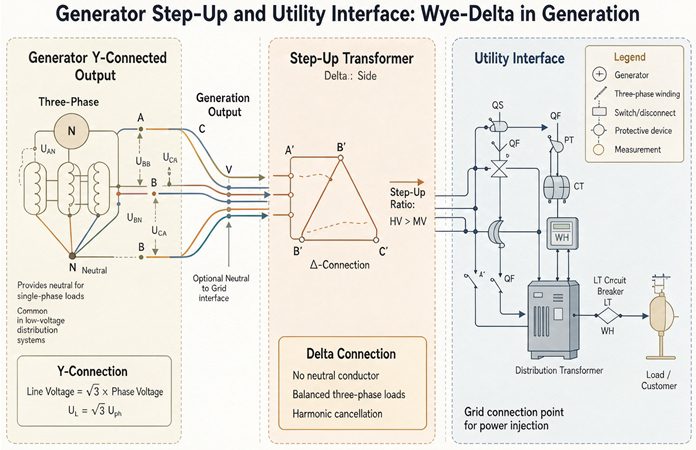
A generator step-up transformer is named from the grid end. The high side is wye, solidly grounded. The generator side is delta, with no neutral to bring out. That single choice is what lets a plant run a 10 amp stator ground fault limit and still hand the utility an effectively grounded source at the point of interconnection.
That sentence is worth more than it looks, because it explains both halves of the title in one move. The wye-delta connection is not a convention somebody picked in a committee. It is the only arrangement that lets two grounding systems with opposite requirements sit on the same core, one on each side, without either of them knowing about the other.
The confusion starts earlier than that, though, and it starts with the name. Search for a wye-delta generator transformer and half the results describe a delta primary. Both descriptions are correct. They are describing the same machine from opposite ends, because the American convention calls the generator winding the primary and the IEC convention writes the high voltage winding first. Get the two confused on a purchase order and you can end up with a transformer that is 60 degrees out of phase with the plant next door.
What follows is the interface in the order a specification reviewer needs it. What the name actually means and how to read it off the tank. Why the grid side is wye, proved from the insulation rather than the tradition. Why the generator side is delta, proved from the fault current rather than the brochure. Then the parts that decide whether the interconnection study passes: the turns ratio that is not the nameplate ratio, the 30 degrees and where it costs money, the impedance number, and the seven items the utility will actually ask about.
The name on the drawing is not the name on the nameplate
Open any generating station single line diagram in North America and the unit transformer is labeled delta-wye. Open the nameplate on the same unit and it reads YNd11. Open a datasheet from a European manufacturer for the same duty and it is described as a wye-delta transformer.
All three are the same object. The difference is which end you start from.
Under IEC 60076-1 the vector group symbol always writes the high voltage winding first. A capital letter is the high side, a lower case letter is the low side, N means the neutral is brought out, and the number is the clock position of the low side relative to the high side. So YNd11 reads: high voltage wye with a neutral, low voltage delta, low side leading by 30 degrees.
Under the North American habit, the winding connected to the generator is called the primary, because that is where the power comes from. The generator is at 18 kV and the grid is at 230 kV, so the primary is the low voltage winding and it is delta. That gives delta-wye.
| What it is called | Who says it | Which end is named first | The machine |
|---|---|---|---|
| Wye-delta, Y-Δ | IEC vector group practice, most of the world | High voltage | 230 kV wye, 18 kV delta |
| Delta-wye, Δ-Y | North American plant drawings | Generator | 18 kV delta, 230 kV wye |
| YNd11 | The nameplate | High voltage, with the clock | 230 kV grounded wye, 18 kV delta, low leads by 30 degrees |
| YNd1 | The nameplate, alternative | High voltage, with the clock | Same windings, low lags by 30 degrees |
| Delta primary | The datasheet from a supplier who builds to UL | Generator | 18 kV delta |
Five names, one transformer. The mistake this causes is not academic. If you write delta-wye on an enquiry to a supplier who builds to IEC and you mean the generator end is delta, you get what you asked for and it is right. If you write wye-delta and you mean the grid end is wye, you also get what you asked for. But if you write one and think the other, you get a transformer whose low side is wye, which means a neutral bushing you did not plan for, a zero sequence path into your stator that you did not want, and a winding ratio that is wrong by a factor of 1.732.
There is a field check that takes ten seconds and needs no paperwork. Count the bushings on the tank. A three phase unit with a delta on one side and a grounded wye on the other has seven: three on the delta side, three on the wye side, and one neutral. A unit with wye on both sides has eight, because the second neutral has to come out somewhere. A unit with delta on both sides has six. If the count does not match the drawing, stop before you order the cable.
The guide that covers this transformer leaves the two hardest questions out
IEEE C57.116 is the guide for transformers directly connected to generators, and the 2022 revision covers exactly this duty: the unit power transformer and the unit auxiliary transformer, connected either directly to the generator or through a generator circuit breaker or load break switch, in hydro and thermal stations.
Its scope statement is unusually honest. It says the guide does not cover phasing procedures, basic impulse insulation level selection, or loading practices. Those three exclusions are the three things that most often go wrong on a generator interconnection, which means the standard tells you what to consider and then declines to decide the two numbers your specification has to carry.
That is not a criticism of the guide. It is a warning about where to look. The vector group is a plant wide decision, the BIL is an insulation coordination decision, and the loading is a system study decision. None of them live inside the transformer standard, and none of them can be delegated to the supplier.
Reading YNd11 in one pass
The five characters carry four separate facts, and each one has a physical consequence you can point at.
Y. The high voltage winding is wye connected. Three windings meet at a common point. The voltage across each winding is the line to line voltage divided by 1.732, and the current through each winding is the line current. On a 200 MVA, 230 kV unit that is 132.8 kV per winding and 502 A per winding.
N. The neutral point is brought out to a bushing. This is the single most consequential letter in the group, because it decides whether the utility sees a grounded source or a floating one. Without the N, the wye is ungrounded and the utility has no zero sequence source at the point of interconnection.
d. The low voltage winding is delta connected. Three windings in a closed loop, no neutral, no fourth wire. Each winding sees the full line to line voltage of 18 kV and carries 57.7 percent of the line current, which is 3,704 A on a 200 MVA unit.
11. The low voltage line voltage leads the high voltage line voltage by 30 degrees. Clock 11 is 330 degrees clockwise from 12, which is the same as 30 degrees counterclockwise, which is a lead. Clock 1 would be a lag of 30 degrees.
Two of those facts are load bearing and two are bookkeeping. The N decides the utility interface. The d decides what happens to a stator ground fault. The Y and the 11 are consequences of those two choices that you then have to live with.
Both clock positions are real, which is the annoying part
Clock 1 and clock 11 both appear on real generator step-up nameplates. The difference between the two is 60 degrees, and 60 degrees is enough to stop two units from being paralleled, enough to block a closed transition transfer, and enough to change the settings in a distance relay scheme.
There is a piece of published guidance that states clock 1 as a lead of 30 degrees. That is backwards. By the clock face convention, the low side phasor sits at the hour, the high side sits at 12, and moving clockwise from 12 means the low side is later in time, which means it lags. Clock 1 lags. Clock 11 leads. One of the most widely repeated explanations on the open web has this reversed, so check it against a phasor diagram before you copy it into a relay setting sheet.
The practical rule for a plant is narrower than the standards argument. Your unit transformer and your unit auxiliary transformer both hang off the generator bus. If they carry different vector groups, the auxiliary bus and the grid are not in phase, and you cannot transfer the station service load between them with a closed transition. That is a commissioning day problem, not a design review problem.
Why the grid side is wye
The wye on the high side is usually explained as a grounding requirement. That is true and it is the second reason. The first reason is cheaper and more basic: insulation.
The insulation argument, in one table
A transformer winding has to be insulated from the core and the tank, not just from the other windings. In a delta, the whole winding sits at line to line potential with respect to ground, because there is no neutral point to anchor it. In a grounded wye, the winding is anchored at the neutral, so the highest steady state voltage any point on that winding sees to ground is the phase voltage, which is 57.7 percent of the line voltage.
That difference moves the unit down a whole voltage class, and the voltage class is what sets the basic impulse insulation level, and the BIL is what sets the clearance, the lead insulation, the bushing class, and a good part of the tank size.
| System voltage | Delta high side | Grounded wye high side | BIL saved |
|---|---|---|---|
| 230 kV | 230 kV class, BIL 900 kV | Phase to ground 132.8 kV, 138 kV class, BIL 650 kV | 27.8 percent |
| 345 kV | 345 kV class, BIL 1,175 kV | Phase to ground 199.2 kV, 230 kV class, BIL 900 kV | 23.4 percent |
| 500 kV | 500 kV class, BIL 1,550 kV | Phase to ground 288.7 kV, 345 kV class, BIL 1,175 kV | 24.2 percent |
The numbers in that table come from the standard BIL steps in IEEE C57.12.00: 350 kV for 69 kV, 550 for 115, 650 for 138, 750 for 161, 900 for 230, 1,175 for 345, 1,550 for 500.
Read the last column and the rest of this section follows. A delta connected 230 kV winding needs 900 kV of BIL because every point on it is 230 kV away from ground. A grounded wye at the same system voltage needs 650 kV, because no point on it is more than 132.8 kV away from ground. That is a 38.5 percent reduction in the insulation level of the most expensive part of the transformer, and it is available only if you bring the neutral out and ground it.
This is also why nobody builds a 230 kV delta. It is not forbidden. It is simply a 230 kV class winding doing a job that a 138 kV class winding can do, and you would pay for the difference in bushings alone.
The grounding argument, which is the one the utility cares about
The second reason is that the utility needs a zero sequence source. Almost every transmission system above 100 kV is effectively grounded, and effective grounding is a measurable property, not a slogan.
The screen is simple. A source is effectively grounded if the ratio of zero sequence reactance to positive sequence reactance is 3 or less, and the ratio of zero sequence resistance to positive sequence reactance is less than 1. Both conditions, not either one. The underlying physical test is that a single line to ground fault on any phase should not push the other two phases above 80 percent of the line to line voltage, which is where the coefficient of grounding number comes from.
A grounded wye transformer passes that screen almost by construction. Its zero sequence impedance at the terminals is the leakage impedance, same as the positive sequence, because the delta on the other side gives the zero sequence current somewhere to go. So X0/X1 comes out at about 1.0, and the margin against the limit of 3 is the whole width of the limit.
A generator does not pass it, and cannot. That is the other half of the story, and it is the reason the delta exists.
Why the generator side is delta
Start with what a stator ground fault does to a machine. The fault current has to come from somewhere, and in a solidly grounded generator it comes from the generator itself, through the fault, back to the neutral. The current lands in the laminated stator core at the fault point, and the core is the part of the machine that cannot be repaired in place.
IEEE C62.92.2, the guide for grounding synchronous generator systems, states the mechanism plainly: iron burning and damage depend mainly on fault current magnitude and duration. That is why the guide points at a ground fault current of 5 to 25 A for high resistance grounding rather than at a percentage of the machine rating. Ten amps is the number most plants land on.
Now run the arithmetic on a 200 MVA, 18 kV machine with a subtransient reactance of 18 percent and a zero sequence reactance of 8 percent.
| Case | Ground fault current | What it does to the core |
|---|---|---|
| Solidly grounded | 43,739 A | Destroys laminations at the fault, requires restacking |
| 10 A neutral resistor | 10 A | Scorches paint, usually repairable in place |
| Delta isolated, no ground reference | Charging current only | Restriking arc overvoltages, up to several times phase voltage |
The solid case is 1.23 times the three phase fault current of 35,639 A, which surprises people who assume a ground fault is always the smaller event. It is not. Zero sequence impedance is usually the lowest of the three sequence impedances in a generator, so the single line to ground fault is often the worst case for the core.
The delta does not create the 10 A. The neutral grounding resistor does that. What the delta does is make the resistor matter, because it removes the path by which a ground fault on the high voltage side could reach the stator at all.
One fault, two very different currents
Picture a single line to ground fault on the 230 kV side of the transformer, out on the transmission line a few spans away. The utility’s protection sees it and clears it in a few cycles. The question for the plant is what the generator saw during those cycles.
With a delta on the generator side, the answer is: no zero sequence current at all. The delta winding has no neutral, so the zero sequence current induced in it has nowhere to leave the winding. It circulates inside the delta and cancels. The generator contributes positive and negative sequence current to the fault, which is an unbalanced load, but nothing flows through the stator to ground.
With a grounded wye on the generator side, the answer is different. The generator neutral is now part of the fault circuit. Zero sequence current from a fault a mile away on the transmission system can return through the GSU’s high side neutral, through the transformer, and out through the generator neutral, which means it passes through the stator core on the way.
That is the whole point of the connection, and it is why the delta is on the generator end and not on the grid end. The grid needs the neutral. The generator cannot have it.
The third harmonic comes along for the ride
There is a second, quieter benefit that shows up in power quality measurements rather than in a fault study.
A transformer core saturates a little differently on each half cycle, which generates a third harmonic magnetizing current. Third harmonic currents in three phases are all in phase with each other, so they add arithmetically rather than cancelling. In a delta winding they have a closed path and circulate inside it, which keeps them out of the line current. In a wye winding they have to go somewhere, and if the neutral is grounded they go into the neutral and from there into the utility’s ground protection.
A GSU with a delta on either side traps its own triplen harmonics. A wye-wye unit with both neutrals grounded does not, and the utility’s residual current relays see a standing third harmonic current that has nothing to do with a fault.
That is the reason the delta is never removed for convenience, even on the small units where the fault current argument is weaker.
Two grounding systems in one transformer
Here is the part that most explanations skip, and it is the reason the connection exists.
A generator wants to be resistance grounded. A transmission system wants to be effectively grounded. Those two requirements are not just different, they are on opposite sides of a screen that a utility applies with a calculator, and a plant with one transformer has to satisfy both at the same time.
The screen has two parts, and both have to pass. Zero sequence reactance over positive sequence reactance must be 3 or less. Zero sequence resistance over positive sequence reactance must be less than 1.
Run the generator first. A 200 MVA, 18 kV machine with a subtransient reactance of 18 percent and a zero sequence reactance of 8 percent, grounded through a resistor sized for 10 A.
The base impedance is 1.62 ohms. The resistor that limits a phase to neutral fault to 10 A is 10,392 volts divided by 10 amps, which is 1,039 ohms, which is 642 per unit. The zero sequence resistance seen at the generator terminals is three times that, because the fault current passes through the resistor once and the return path twice.
So X0/X1 is 0.08 divided by 0.18, which is 0.44 and passes the first test comfortably. And R0/X1 is 1,926 divided by 0.18, which is 10,692, against a limit of 1.
The generator fails the effective grounding screen by a factor of about ten thousand. Not marginally. It is not in the same conversation as the limit.
That is not a design error. It is the whole point of high resistance grounding. A machine that passes the effective grounding screen is a machine that will destroy its own core the first time a winding fails to ground.
Now run the transformer. At the high voltage terminals of a YNd unit, the zero sequence impedance is the leakage impedance, because the delta winding short circuits the zero sequence path on the low side. So Z0 equals Z1 equals 12 percent, and X0/X1 is 1.0.
The transformer passes the screen with two thirds of the allowance unused, and it does so while the machine behind it fails by four orders of magnitude.
This is the sentence to put in the interconnection application
The plant is not effectively grounded at the generator terminals and it is effectively grounded at the point of interconnection, and both statements are true because the delta winding sits between them.
That is what the utility is buying when it specifies a grounded wye high side. It is not asking for a grounding transformer, and it is not asking you to solidly ground the generator. It is asking for a zero sequence source at the boundary, and the GSU is the device that manufactures one out of a source that does not have any.
Put the two numbers side by side in the application and the review gets shorter.
| Quantity | At the generator terminals | At the point of interconnection |
|---|---|---|
| Ground fault current | 10 A, set by the neutral resistor | 4,184 A from the GSU alone at 12 percent |
| X0/X1 | 0.44 | 1.0 |
| R0/X1 | 10,692 | Well under 1 |
| Effectively grounded | No, by design | Yes |
| What sets the number | Stator core damage threshold | Transformer leakage impedance |
Two rows in that table are the argument. The rest is supporting detail.
Where the arrangement breaks, and how to fix it without changing the transformer
The one case that breaks it is the generator bus with no generator on it.
When the unit is down and the plant is being backfed from the grid through the GSU, the 18 kV bus is energized from the delta winding, which has no neutral. The generator is offline, so its neutral resistor is out of service. The bus now has no ground reference at all.
That is not a theoretical condition. It is the normal state of the plant during a maintenance outage, and it is when the auxiliary load is being carried.
The fix is a grounding transformer on the generator bus, usually zigzag, sized for the bus charging current rather than for a fault. A typical unit for an 18 kV bus is 300 to 500 kVA with an impedance around 7 to 9 percent, rated for continuous operation at 5 to 15 A. It does nothing while the generator is running and everything while it is not.
If your single line shows a GSU with a delta low side and no grounding transformer on the generator bus, the design has a hole in it that only appears during an outage. It is a cheap hole to fill at the drawing stage and an expensive one to discover during commissioning.
What the delta does to the turns ratio
The nameplate ratio and the winding ratio are different numbers, and the difference is exactly 1.732.
On a 200 MVA unit at 18 kV and 230 kV, the nameplate says 12.78 to 1. That is 230 divided by 18, and it is the ratio of line voltages. It is not the ratio of turns on any winding in the tank.
The high voltage winding is wye connected, so each phase winding only carries 132.8 kV, not 230 kV. The low voltage winding is delta connected, so each phase winding carries the full 18 kV. The ratio per phase is 132.8 divided by 18, which is 7.377.
Multiply 7.377 by 1.732 and you get 12.778. The two numbers are the same fact viewed from different places.
| Quantity | Delta winding, generator side | Wye winding, grid side | Ratio |
|---|---|---|---|
| Voltage across the winding | 18.0 kV | 132.8 kV | 7.377 |
| Current through the winding | 3,704 A | 502 A | 7.377 |
| Power per phase | 66.7 MVA | 66.7 MVA | 1.000 |
The two windings carry the same power per phase, at the same current density, with the same number of ampere turns per unit of core. What changed is that the delta converted a 6,415 A line current into a 3,704 A winding current, and the wye converted a 230 kV line voltage into a 132.8 kV winding voltage. Both conversions are the same factor, 1.732, applied in opposite directions.
The mistake this catches
A repair shop that rewinds a GSU to the nameplate ratio builds a transformer that puts out 398 kV.
Work it through. A winding at 7.377 to 1 with 18 kV on the primary produces 132.8 kV across the secondary winding. Connect three of those in wye and the line voltage is 132.8 times 1.732, which is 230 kV. Correct.
Now build the same three windings at 12.78 to 1. Each secondary produces 230 kV. Connect them in wye and the line voltage is 398.4 kV. The unit will pass a turns ratio test at the terminals if the tester expects 12.78, because 12.78 is what it will measure, but the winding is now at 230 kV instead of 132.8 kV, which means every insulation distance in the high voltage assembly is being asked to do a job it was not designed for.
This is also why the factory ratio test is done per phase and reported against the winding ratio, not just as a single line to line number. Ask for the per phase figures. If they match the nameplate ratio instead of the winding ratio, the test report is being written by someone who has not looked at the connection.
Why the low side current is 57.7 percent of the bus current
On the generator side, the delta winding current is the line current divided by 1.732. That is 3,704 A against a bus current of 6,415 A, or 57.7 percent.
That number decides the busbar, the isolated phase bus, the generator circuit breaker, and the low voltage bushings, all of which are sized on the 6,415 A line current and none of which can be sized on the 3,704 A winding current. It also explains why the delta winding looks under built next to the connection it serves. It is not. The conductor is carrying the current the winding was designed for.
The same relationship appears on the high side in voltage form. The wye winding sees 57.7 percent of the line voltage. Both sides are running at 57.7 percent of the terminal quantity, which is what makes the per phase powers match.
When the low side is wye instead
A synchronous plant can use a wye low side, and some do. The trade is straightforward. You gain a neutral on the generator side, which lets you serve plant loads at 277 V or 347 V directly from the generator bus and gives the generator a solid ground reference without a separate grounding transformer. You lose the zero sequence block, which means a ground fault on the high side now has a path into the stator, and you lose the third harmonic trap unless you add a delta tertiary.
Inverter based plants almost never take that trade. The DC link in a wind or solar inverter injects more harmonic current than a synchronous machine does, and the delta is the cheapest harmonic filter in the station. That is why the equipment on a solar or wind site is almost always delta on the inverter side even when a gas plant next door is wye.
The 30 degrees, and where it costs money
The 30 degree shift is a consequence of mixing a wye and a delta on the same core. It is not a defect and it does not stop the plant connecting to the grid. The synchroscope handles the generator to grid angle, and the utility’s phasing procedure handles the rest.
What the shift does stop is anything that connects two sources to each other without a transformer in between.
Parallel operation
Two transformers can only be paralleled if their vector groups match. Not their voltage ratios, not their impedances, their vector groups. A YNd11 unit and a YNd1 unit differ by 60 degrees, and 60 degrees is enough to destroy both of them if you close the tie.
The arithmetic is short. Two sources at 60 degrees apart with equal magnitude have a voltage difference of 1.0 per unit, because the chord of a 60 degree arc on a unit circle is 1.0. Push that difference through a tie with 10 percent impedance and the current is 10 per unit.
Ten times full load current, from two healthy transformers, with no fault anywhere on the system.
At 30 degrees apart the difference is 0.518 per unit and the current is 5.2 per unit, which is survivable for a few cycles but will still trip a differential relay and will certainly be reported as a fault.
This matters at a plant with two units and a common high voltage bus, and it matters more at a plant that is adding a second unit next to an existing one built by a different EPC under a different standard. The new unit’s vector group has to match the old one, and the old one’s nameplate is the only authority.
Auxiliary transfer
The unit auxiliary transformer and the GSU both hang off the generator bus. During a unit start, the auxiliary load is carried by the station service transformer, which is fed from the grid. Once the unit is at speed, the load transfers to the unit auxiliary transformer, which is fed from the generator.
If those two sources are not in phase, the transfer has to be a break before make, which means a brief outage on the auxiliary bus, which for a large boiler means a trip. If they are in phase, the transfer can be made with both breakers closed for a few cycles, and the bus never sees an interruption.
Getting them in phase means the GSU and the UAT have to present the same phase relationship to the generator bus. That is a vector group decision made once, at the front end, and it is almost impossible to fix afterward without replacing a transformer.
Backfeed and the overexcitation relay
The GSU is bidirectional. Power normally flows from the generator up to the grid, and during a unit outage it flows the other way to supply the auxiliary load.
Backfeed is where the connection earns its keep and where it creates a new problem. With the generator offline, the high side voltage is set by the grid, and the low side voltage is the grid voltage divided by the turns ratio. If the grid is running 5 percent high and the tap is set for nominal, the generator bus is also 5 percent high, and the auxiliary motors see it.
The relay that watches this is the volts per hertz element, ANSI 24. Its input is voltage in per unit divided by frequency in per unit, and a transformer’s core saturates when that quotient gets too large, regardless of which side is driving it.
A 230 kV bus at 1.05 per unit voltage and 60 Hz is 1.05 on the V/Hz curve, which is the continuous limit. Drop the frequency to 58 Hz with the same voltage and the quotient is 1.05 divided by 0.967, which is 1.086. That is inside the short time region, on a transformer with nothing wrong with it, because the grid frequency moved.
A plant that is required to ride through a frequency excursion while the transmission system is running high will trip on the GSU’s overexcitation relay if the setting was copied from a unit that never backfed. Set the 24 element on the transformer capability curve, and coordinate it with the ride-through requirement rather than against it.
Protections that care, in one table
| ANSI device | What it watches | Why the connection matters |
|---|---|---|
| 87T | Transformer differential | The 30 degree shift and the 1.732 magnitude difference have to be compensated, in the relay or in the CTs |
| 87G | Generator differential | Unaffected by the vector group, but the CTs on the generator side sit on the delta side of the shift |
| 51N / 51G | Ground overcurrent | The GSU neutral CT sees only high side ground faults, the generator neutral CT sees only stator faults |
| 64G | Stator ground | Set by the neutral resistor, which is only meaningful because the delta blocks the other path |
| 32 | Reverse power | Watches the GSU for motoring, which is a normal transient and an abnormal event depending on duration |
| 24 | Volts per hertz | Set by the core, driven by whichever side is energized |
| 78 | Out of step | Watches the angle across the GSU plus the line, and the GSU impedance is part of that angle |
The 87T row is the one that eats commissioning time. The compensation is routine in a numerical relay, and the mistake is routine too: leaving the CTs delta connected on the wye side when the relay expects wye connected CTs and does the rotation in software. The relay then sees a magnitude error of 1.732 and an angle error of 30 degrees, both of which look like a fault.
If the CTs are wye connected on both sides and the relay does the compensation, the only thing the field crew has to get right is the CT ratio and the star point. If the CTs are delta connected on one side, the field crew has to get the DAB versus DAC connection right as well, and that is where the 60 degree errors come from.
Impedance: what 12 percent actually buys
Generator step-up units typically land between 10 and 14 percent impedance. The number is not free. It is bought and sold in three currencies, and only one of them is usually discussed.
The first currency is fault current. On a 200 MVA unit at 230 kV, 12 percent gives 4,184 A at the high voltage terminals. Ten percent gives 5,020 A. Fourteen percent gives 3,586 A. None of those numbers is interesting to a 230 kV breaker rated at 40 kA, which is why the utility’s switchgear is almost never the constraint on a GSU.
The second currency is voltage regulation. At full load and 0.95 power factor, 12 percent impedance drops 4.22 percent across the unit. At 0.90 power factor it drops 5.68 percent. Against a plus or minus 5 percent band at the point of interconnection, that leaves 0.8 percent of margin at full load and 0.95 power factor, and it leaves negative margin at 0.90.
That is the real reason GSUs are ordered with the nominal tap at 102 percent of system voltage. The tap is not correcting for a design error. It is buying back the 4.2 percent that the impedance spends at full load.
The third currency is transient stability, and this is where the published advice and the arithmetic part ways.
The stability argument, checked
Lower impedance raises the maximum power a generator can push into an infinite bus, because maximum power is generator voltage times bus voltage divided by the total reactance between them. At 10 percent the unit alone can deliver 10 per unit. At 12 percent it can deliver 8.33. At 14 percent it can deliver 7.14.
Those numbers make a compelling case for 10 percent until you add the rest of the network. A 200 MVA plant connecting through 200 km of 230 kV line has about 0.35 per unit of line reactance, and the system behind the interconnection contributes about 0.10. Total reactance at 12 percent is 0.57 per unit, and the maximum power is 1.754 per unit.
Move the GSU to 14 percent and the total becomes 0.59, and the maximum power becomes 1.695 per unit. That is a 3.4 percent change in the transfer limit, not a 14 percent change.
| GSU impedance | Unit alone, maximum power | With 0.35 pu line and 0.10 pu system | Angle at 0.95 pu |
|---|---|---|---|
| 10 percent | 10.00 pu | 1.818 pu | 31.5 degrees |
| 12 percent | 8.33 pu | 1.754 pu | 32.8 degrees |
| 14 percent | 7.14 pu | 1.695 pu | 34.1 degrees |
Twelve to fourteen percent costs 3.4 percent of the system transfer limit and 14.3 percent of the unit’s standalone limit. Both numbers are true, and only the first one matters to the grid.
So the stability argument for a low impedance GSU is real in a plant that connects directly to a strong bus with no line, and it is second order in a plant that connects through 200 km of transmission. If someone is arguing for 10 percent on stability grounds, ask what the line impedance is. If the answer is more than about 0.2 per unit, the argument is about something else.
What the impedance is really buying, in most specifications, is the fault current the generator bus has to survive. That is the next section.
The tap changer, and why it is usually a DETC
A GSU almost always ships with a de-energized tap changer, not an on-load one. The reason is that the generator already has a voltage regulator, and two regulators in series on the same quantity will fight.
The generator’s automatic voltage regulator holds terminal voltage within about plus or minus 5 percent, continuously, in real time. The GSU’s tap only has to correct for the slow drift: the seasonal grid voltage, the change in generator capability as the machine ages, and the difference between the nameplate ratio and the actual system voltage. None of those needs to happen under load.
A five position DETC at 2.5 percent per step spans plus or minus 5 percent, which at 230 kV is 11.5 kV of range in 2.88 kV steps. With the tap set at 102 percent nominal, which is the common North American practice for an independent power project, the unit starts with about 4.6 kV of headroom above nominal and spends it at full load.
An on-load tap changer on a GSU is not wrong, but it is a different machine. It adds 15 to 30 percent to the transformer price, adds a maintenance item on the busiest accessory in the unit, and it only makes sense where the grid code requires the transformer itself to regulate voltage rather than the generator. In a market where voltage support is a paid service, that can be worth it. In a plant that sells energy at a fixed power factor, it is a cost with no revenue attached.
The number worth knowing is how rarely it is specified. One published survey of more than 120 independent power plant generators installed over 32 years found that about four specified an on-load tap changer. The rest used a five position de-energized tap at 2.5 percent per step, with the nominal position set at 102 percent of system voltage.
The utility interface, item by item
The interconnection agreement is where the connection stops being a transformer decision and becomes a contract. Seven items come up in almost every review, and six of them are decided by the transformer.
One: the voltage band at the point of interconnection
The utility will name a band, usually plus or minus 5 percent of nominal, sometimes tighter. Your job is to show that the plant stays inside it across the full range of generator output and power factor.
The GSU spends 4.22 percent of that band at full load and 0.95 power factor, and nothing at no load. So the point of interconnection voltage moves about 4.2 percent between a cold start and full output, before the grid moves at all. If the utility’s band is plus or minus 5 percent and the grid is already 3 percent high, the plant cannot hold the band at full load with the tap at nominal.
The two levers are the tap position and the generator’s reactive capability. The tap is free and set once. The reactive capability is a contract term, because absorbing or producing VARs at the boundary is usually priced.
Two: the effective grounding demonstration
The utility will ask you to show that the plant presents an effectively grounded source at the point of interconnection. That is the X0/X1 and R0/X1 screen from earlier, computed at the boundary rather than at the generator.
With a YNd unit, the answer is 1.0 and the review closes. With a Yy unit and a resistance grounded generator, the answer depends on the utility’s own source impedance in parallel with yours, and it can fail if the plant is a large fraction of the local fault level. That is the case where a delta tertiary or a zigzag grounding transformer on the high side gets added, and it is a change order on a transformer that was already released for manufacture.
Ask for the screen before you release the design. It is two divisions and it decides the winding connection.
Three: the vector group against the utility’s existing plant
Most utilities have a standard vector group for generation interconnections, and it exists so that two plants on the same bus can be paralleled and so that the utility’s protection settings transfer from one plant to the next.
If your plant is the first on a new substation, you may get to choose, and the choice should match whatever the utility expects the next plant to use. If your plant is the second, you do not get to choose. The existing plant’s nameplate decides, and your GSU has to match it.
This is the item most often missed in a competitive tender, because the enquiry goes out before the utility’s interconnection study comes back and the vector group is left as “per utility requirement.” That phrase has cost more than one project a replacement transformer.
Four: reverse power and motoring
A GSU is a bidirectional device, and when the generator trips with the high side breaker closed, the grid backfeeds the unit and the generator motors.
The relay is ANSI 32, set somewhere between 0.5 and 2 percent of rated output, which on a 200 MVA unit is 500 to 2,000 kW. That band exists because the real event is not always a trip. A steam turbine that loses steam flow but stays online will motor on the grid, and the exhaust hood will overheat within minutes at low flow. A gas turbine that loses fuel will motor the generator and drive the turbine from the wrong end.
The setting has to be low enough to catch a genuine motoring event and high enough to ride through the reverse power that appears during a normal synchronization, when the generator is briefly absorbing a small amount of power before the governor picks up load.
Five: voltage and frequency ride-through
For a transmission connected plant, the ride-through obligation comes from the transmission operator and from NERC PRC-024, which sets the voltage and frequency protection settings a generating unit has to use so that it does not trip during a disturbance the bulk system is designed to survive.
For a distribution connected plant, IEEE 1547-2018 sets the ride-through categories, and the authority governing interconnection requirements assigns the category. The important structural difference is that 1547 tells the plant it must stay connected inside a defined envelope, which is the opposite of the 2003 edition that told it to trip.
Either way, the GSU has to survive the same event, and the two elements that decide whether it does are the overexcitation relay from the backfeed case and the transformer’s through-fault capability. A unit that is required to ride through six voltage dips a year accumulates through-fault duty that a unit built for four dips did not.
Six: backfeed capability, in writing
Ask whether the interconnection agreement requires the plant to be able to backfeed the auxiliary load from the grid through the GSU. Most do, because the alternative is a separate station service transformer fed from the transmission bus, which is a second high voltage bay.
Backfeed changes three things. It puts the GSU’s low side at whatever voltage the grid is at, divided by the tap ratio. It puts the volts per hertz element in play. And it means the delta low side has to have a ground reference from somewhere other than the generator, which is the grounding transformer from earlier.
Seven: metering and the CT ratio
The utility meters at the point of interconnection, and the CT ratio it specifies is usually chosen for the plant’s maximum export plus a margin, not for the transformer’s rating.
On a 200 MVA unit at 230 kV, the line current is 502 A. A utility that specifies 600:5 CTs gets a secondary current of 4.18 A at full output, which is fine for metering and marginal for protection. A utility that specifies 1,200:5 gets 2.09 A, which is comfortable for the meter and too low for a relay that needs to see a 10 percent fault.
The number to check is not the ratio, it is the secondary current at the plant’s minimum and maximum output, against the relay’s and the meter’s specified ranges. A revenue meter wants 1 to 5 A. A distance relay wants more than 1 A at the minimum fault it has to detect.
Where the fault current actually comes from
Most people assume the worst fault on a generator bus comes from the generator. On a unit connected through a GSU, it usually does not.
The generator contributes through its own subtransient reactance. A 200 MVA machine at 18 kV with 18 percent subtransient reactance contributes 35,639 A at its terminals. That is the number in the generator data sheet and it is the number everybody remembers.
The grid contributes through the GSU, and the GSU is a much stiffer path than the generator. At 12 percent impedance on a 200 MVA base, a 10,000 MVA source behind it looks like 0.02 per unit, so the series combination is 0.14 per unit and the current at the 18 kV bus is 45,821 A.
Add them. The 18 kV bus sees 81,460 A, and 56 percent of it comes from the utility, through a transformer, from a fault a hundred miles away.
| Source | Contribution at 18 kV | Share of the total |
|---|---|---|
| Generator, 18 percent subtransient | 35,639 A | 44 percent |
| Grid at 10,000 MVA, through a 12 percent GSU | 45,821 A | 56 percent |
| Grid at 20,000 MVA, same GSU | 49,346 A | 58 percent |
| Total, 10,000 MVA case | 81,460 A | 100 percent |
This is why the generator circuit breaker is a generator circuit breaker and not a switchgear breaker. IEEE C37.013 covers them, and the ratings go to 100 kA and beyond at 24 kV, because a unit connected to a strong grid has to interrupt a fault that is mostly the grid’s.
It is also why the GSU’s impedance is not free to be chosen for stability alone. Raising it from 12 to 14 percent reduces the grid’s contribution from 45,821 to 41,116 A, which is 4,705 A off the bus fault. That may be the difference between a standard breaker and a special order, and it is a better reason to specify 14 percent than a stability calculation that moves by 3.4 percent.
The high side is the other way around. At 230 kV the GSU contributes 1,673 A to a fault, against a breaker rated at 40 kA. The unit is invisible to the transmission protection, which is why the utility spends its review on the generator bus and its studies on the plant, and almost none of it on the transformer’s contribution to the grid.
The small plant, and the neutral that has nowhere to go
Everything above is written around a 200 MVA unit at 18 kV, and the same logic applies at 2,500 kVA and 480 V, with one extra problem that the large plant does not have.
Take a 2,500 kVA pad-mounted unit stepping 480 V up to 12,470 V grounded wye. It is a real configuration, sold as a GSU for gas generator sets and CHP plants, and the numbers are modest.
| Quantity | Value |
|---|---|
| Low side line current | 3,007 A |
| Low side winding current, delta | 1,736 A |
| High side line current | 115.7 A |
| Winding ratio per phase | 15.00 to 1 |
| Nameplate ratio | 25.98 to 1 |
| Low side fault at 5.75 percent | 52,296 A |
| High side fault at 5.75 percent | 2,013 A |
A 2,000 kW generator set at 0.8 power factor is 2,500 kVA, so the transformer is at 100 percent before the plant’s own auxiliary load is counted. That is a sizing mistake worth flagging on its own: the GSU has to be sized for the generator’s rated kVA plus the auxiliary load the generator carries when the plant is islanded, not for the generator’s kW.
The 480 volt generator is almost always wye
Here is the trap. A 2,000 kW standby or prime power generator at 480 V is almost always wound 480Y/277, with a neutral brought out, because that is how the alternator is built and because the set has to be able to serve 277 V lighting and receptacles when it runs alone.
The GSU’s low side is delta. There is no neutral terminal on it.
So the generator’s neutral has nowhere to go. Three options, and each one costs something.
| Option | What you get | What it costs |
|---|---|---|
| Leave the neutral floating | An ungrounded generator | Restriking arc overvoltages, several times phase voltage |
| Ground the neutral through a resistor | A 5 to 10 A stator ground fault limit | A resistor, a relay, and no 277 V supply |
| Ask for a wye low side | A 277 V supply and a solid neutral | No zero sequence block, no third harmonic trap |
Leaving the neutral floating is the option that looks free and is not. An ungrounded system that experiences an intermittent ground fault can produce overvoltages of six to eight times normal phase voltage as the arc restrikes, which is why IEEE 242 treats ungrounded operation as a design choice with an insulation cost rather than a way to avoid a resistor.
Grounding through a resistor is the usual answer, and it has a consequence people miss: the 277 V loads now need their own transformer. A 480 V delta to 480Y/277 V unit, sized for the lighting and receptacle load, becomes part of the package.
Asking for a wye low side solves the 277 V problem and gives up the zero sequence block. On a 2,500 kVA unit the fault current argument is weaker than on a 200 MVA unit, so it is a defensible trade. What is not defensible is ordering a delta low side and discovering at commissioning that the alternator’s neutral lug has no home.
The same arithmetic at 480 volts
The generator grounding numbers scale, which is a useful check.
A 2,500 kVA, 480 V machine with 15 percent subtransient reactance and 6 percent zero sequence reactance has a full load current of 3,007 A, a three phase fault of 20,047 A, and a solidly grounded single line to ground fault of 25,059 A. Again the ground fault is larger than the three phase fault, by 25 percent this time, for the same reason as before.
A 5 A neutral resistor is 277 volts divided by 5 amps, which is 55.4 ohms. In per unit terms that is 601, and R0/X1 comes out at 12,028 against a limit of 1.
Same structure, same failure, four orders of magnitude. A plant engineer who understands the 480 V case understands the 18 kV case, which is the useful part.
Who owns the rules
The last interface question is not electrical. It is who has jurisdiction over the installation, and the answer changes which codebook the inspector carries.
The National Electrical Code excludes installations under the exclusive control of an electric utility, where those installations are on property the utility owns or leases for generation, transformation, transmission or distribution. That exclusion is in Article 90.2(B)(5), and it decides a surprising amount.
| Ownership | Governing documents | What it means in practice |
|---|---|---|
| Utility owned plant | NESC, the utility’s own standards, IEEE C57.12.10 and C57.116 | No NEC inspection, no Article 450 calculation, the utility’s standard detail wins |
| Merchant or IPP plant | NEC, plus the utility’s interconnection tariff, plus NFPA 70E for work practices | Article 450 applies, and so does the utility’s review |
| Behind the meter generation | NEC, plus NFPA 110 for the emergency system, plus the utility’s tariff | The generator is a load side asset until it exports |
The transformer itself does not change. A 200 MVA, 230 kV unit built to IEEE C57.12.10 is the same product standard in all three rows, because C57.12.10 covers liquid immersed power transformers of 750 kVA and above used for step-up or step-down, and it does not care who owns the plant.
What changes is everything around it. On a utility owned plant, the high side connection is designed to the NESC and the utility’s substation standard. On an IPP plant, the same connection is designed to the NEC, which means Article 450 applies to the transformer protection and the working clearances in Article 110.26 apply to the switchgear.
The electrical boundary is the point of interconnection. The code boundary is the ownership line, and the two do not always coincide. If the utility owns the high side breaker and you own the transformer, you have two codebooks meeting at a bushing, and the interconnection agreement has to say which one governs which side.
One more split worth knowing: inside the NEC, the transformer protection rules change at 1,000 V. Above 1,000 V it is Article 450.3(A), below it is 450.3(B), and the percentages and the next size up allowances are different tables. A 12,470 V GSU primary and a 480 V GSU primary are not the same calculation even when the kVA is identical.
The numbers on one page
If you are checking a specification against this page, these are the figures worth carrying into the review.
| Item | Value | Where it comes from |
|---|---|---|
| High side connection | Grounded wye, neutral brought out | Effective grounding screen at the point of interconnection |
| Low side connection | Delta, no neutral | Stator core protection, third harmonic trap |
| Vector group | YNd11 or YNd1, matching the utility and the UAT | Nameplate, not the drawing |
| BIL on the high side | One voltage class below the system voltage | IEEE C57.12.00 BIL steps |
| Winding ratio | Nameplate ratio divided by 1.732 | Wye on one side, delta on the other |
| Impedance | 10 to 14 percent | Fault current at the generator bus, plus regulation |
| Tap | Five position DETC, 2.5 percent per step, nominal at 102 percent | AVR does the regulating |
| Generator grounding | 5 to 25 A, 10 A typical | IEEE C62.92.2 |
| Grounding transformer | 300 to 500 kVA zigzag, 7 to 9 percent | Needed only when the unit is backfed |
| Reverse power setting | 0.5 to 2 percent of rating | ANSI 32 |
| Volts per hertz | Voltage pu divided by frequency pu | ANSI 24, set on the transformer curve |
What to put in the enquiry
A generator step-up enquiry that leaves the vector group to the supplier will get a transformer. It will not get the right one.
Put these eleven lines in the datasheet, in this order, and most of the arguments disappear before the bids come back.
| Line | What to write | Why it matters |
|---|---|---|
| 1 | Rated MVA, generator voltage, system voltage, and the winding connection of each | The ratio is not the nameplate ratio, and the connection decides everything else |
| 2 | Vector group, with the clock number, and the utility’s reference document | A 60 degree error is not fixable downstream |
| 3 | BIL for each winding, with the insulation coordination study reference | The delta or wye decision moves the class |
| 4 | Impedance at the rated MVA base, with the tolerance | The generator bus fault current depends on it |
| 5 | Tap range and step, and the nominal position as a percentage of system voltage | 102 percent is a decision, not a default |
| 6 | Cooling stage that defines the rating, and the ambient | A GSU runs at rated output whenever it runs |
| 7 | Guaranteed no-load and load losses, at a stated reference temperature | Load loss at 75 °C and at 120 °C are different numbers |
| 8 | Through-fault duty, in dips per year and duration | Ride-through obligations accumulate |
| 9 | Sound level in dB(A) at 1 m, and the measurement standard | A GSU is often the closest transformer to a fence |
| 10 | Test list, including a per phase ratio test with the winding ratio stated | Catches the 12.78 mistake at the factory |
| 11 | Whether the unit must backfeed the auxiliary load, and at what voltage | Decides the grounding transformer and the 24 relay |
Line ten is the one that costs the least and catches the most. A per phase ratio test reported against the winding ratio, with the connection stated on the report, is a two minute test that has caught real errors in real factories.
Commissioning checks that catch the expensive mistakes
Five checks, in the order they should happen. None of them takes more than an hour, and each one catches a mistake that costs a transformer or a forced outage.
Count the bushings before you unpack. Seven on a YNd unit, eight on a Yy, six on a Dd. If the count is wrong, the unit is wrong, and the argument is with the factory rather than with the field crew.
Measure the ratio per phase, not line to line. The per phase number should be the nameplate ratio divided by 1.732. If it matches the nameplate ratio, the winding has the wrong turns and the unit will produce 398 kV instead of 230.
Check the vector group with a three phase source and a phase angle meter. Energize the high side at reduced voltage, measure the angle between H1 and X1, and compare it with the nameplate clock number. A 30 degree error means a reversed winding. A 60 degree error means the wrong group entirely.
Verify the CT connections against the relay’s expectation. If the relay is set for wye connected CTs on both sides, the CTs have to be wye connected on both sides. If they are delta connected, the relay sees 1.732 times the current and 30 degrees of shift, and the differential element will operate on load.
Test the neutral circuit end to end. Inject current at the generator neutral CT and confirm the 64G element operates, then do the same at the GSU high side neutral for the 51N. A neutral CT with a reversed polarity is invisible until the first ground fault, and by then the core has already taken the current.
The one that gets skipped is the fourth. A differential relay that operates on load is obvious. A differential relay that is 1.732 times too sensitive is not, and it will operate on the first through fault that it should have ridden through.
Bottom line
The wye-delta connection is not a tradition and it is not a preference. It is the arrangement that lets a generator be grounded for its own protection and the grid be grounded for the utility’s, on the same core, with the delta sitting between them doing both jobs at once.
The three numbers that decide whether your plant gets that arrangement right are the vector group on the nameplate, the BIL the connection allows, and the impedance that sets the fault current at the generator bus. The first is a naming problem, the second is an insulation problem, and the third is a fault duty problem. None of them is an efficiency problem, which is why the usual tender comparison does not catch any of them.
The two mistakes worth guarding against are both cheap to prevent. Writing delta-wye on an enquiry to a supplier who writes wye-delta, and ordering a delta low side for a 480 V generator that has a neutral terminal and nowhere to put it. One costs a transformer. The other costs a commissioning week and a second transformer for the 277 V loads.
If you are working through a generator interconnection and the vector group, the BIL or the fault duty is still open, that is the conversation to have before the unit is released for manufacture. It starts here.
FAQ
Why is a generator step-up transformer wye-delta instead of delta-wye?
It is both, depending on which end you name first. IEC practice writes the high voltage winding first, so a unit with a grounded wye high side and a delta generator side is wye-delta. North American plant drawings call the generator winding the primary, so the same unit is delta-wye. There is one machine and two naming conventions.
Which side of a GSU is delta?
The generator side, in almost every case. The delta has no neutral, so a ground fault on the high voltage side cannot drive zero sequence current through the stator. That protects the laminated core, which is the part of a generator that cannot be repaired in place.
Why can’t the high voltage side be delta?
It can be built, and nobody does it above about 115 kV. A delta winding sits at full line to line potential with respect to ground, so a 230 kV delta needs 230 kV class insulation and 900 kV BIL, where a grounded wye at the same voltage needs 138 kV class insulation and 650 kV BIL. The wye saves about 28 percent of the BIL, and it gives the utility the neutral it needs.
What does YNd11 mean on a nameplate?
Y is a wye high voltage winding, N means the neutral is brought out, d is a delta low voltage winding, and 11 is the clock position of the low side relative to the high side. Clock 11 is 330 degrees clockwise, which is a 30 degree lead. Clock 1 would be a 30 degree lag. Both appear on real GSU nameplates.
Why is the generator resistance grounded if the GSU already has a grounded neutral?
Because the GSU’s neutral is on the high voltage side. The delta winding blocks zero sequence from crossing the transformer, so the high side neutral does nothing for a fault in the stator. The generator needs its own neutral resistor, usually sized for 5 to 25 A, to keep a stator ground fault from destroying the core.
Does a GSU need a neutral grounding resistor?
No. The high side neutral is normally solidly grounded, because the utility needs an effectively grounded source at the point of interconnection and a resistor would fail the X0/X1 screen. The resistor belongs on the generator neutral, not the transformer neutral.
What happens if the generator is wye and the GSU low side is delta?
The generator’s neutral has no terminal to connect to. You can leave it floating, which exposes the machine to restriking arc overvoltages, or ground it through a resistor, which protects the stator but leaves any 277 V load without a supply. The third option is to order a wye low side and give up the zero sequence block.
What impedance should a GSU have?
Ten to fourteen percent on the unit’s own MVA base is the usual range. Lower impedance raises the transfer limit but lets more fault current onto the generator bus from the grid. On a 200 MVA unit at 18 kV, 12 percent puts about 81 kA on the bus, and 56 percent of it comes from the utility.
Does a GSU need an on-load tap changer?
Usually not. The generator’s voltage regulator already holds terminal voltage within about plus or minus 5 percent, and a transformer tap changer regulating the same quantity will fight it. A five position de-energized tap at 2.5 percent per step, set at 102 percent nominal, is the common arrangement.
Can two GSUs with different vector groups be paralleled?
No. Vector groups have to match, not just voltage ratios and impedances. Two units 60 degrees apart present a 1.0 per unit voltage difference to the tie, which drives about 10 per unit current through a 10 percent impedance. That is enough to damage both transformers with no fault on the system.