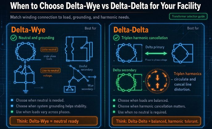
Choose delta-wye when anything on the secondary needs a neutral, which in practice means any 120 V or 277 V load. Choose delta-delta when the load is pure three-wire motors and you want the open-delta fallback. The real switch point is not taste. It is how much unbalanced line-to-neutral current your facility actually has to serve, in amps.
That number has a threshold, and the threshold moves with transformer impedance. On a 5.75 percent unit it lands near 17 percent of nameplate. Below it, the neutral stays stiff and the unbalance argument stops deciding anything, so the choice comes down to load voltages and cost. Above it, delta-delta stops being an option long before anyone looks at a wiring diagram. Most of what gets written about this decision skips that part and stays at the level of “motors or buildings,” which is why so many facilities end up with a transformer that is correct on paper and wrong at the panel.
This article is the version with the numbers attached.
The answer in one paragraph
Delta-wye is the default because almost every modern facility has something that needs a neutral. Roof top units with 277 V control circuits, convenience receptacles, lighting panels, fire alarm panels, the small single phase load in the corner of the shop. Delta-delta makes sense when you can honestly say the secondary feeds nothing but three phase motors, heaters and rectifiers, and when the open-delta fallback has real value to your process. Between those two poles, the deciding evidence is a neutral current calculation and a conductor count, not a preference for one drawing over another.
| What you are deciding | Delta-wye (Dyn1) | Delta-delta (Dd0) |
|---|---|---|
| Neutral on the secondary | Yes, X0 brought out | No |
| Line-to-neutral loads | Any amount, within the unbalance limit | None, without a second transformer |
| Line-to-line single phase loads | Yes, but wasteful | Yes, up to one third of kVA |
| Triplen harmonics from the load | Circulate in the primary delta, kept off the utility | Circulate in both deltas, kept off the utility |
| Triplen voltage on the secondary | Present in phase voltage, absent in line voltage | Absent in both |
| Phase displacement | 30 degrees, lagging on the low side | 0 degrees, or 180 on a Dd6 |
| Single ground fault on the secondary | Clears, because the neutral is grounded | Does not clear, system keeps running |
| Open-delta fallback | Not applicable to a single unit | Yes, 57.7 percent of a three unit bank |
| Typical unit price, same kVA and voltage | Baseline | 3 to 7 percent lower |
| Downstream conductor, per kVA | 11.1 amps | 7.2 amps |
The last two rows are the ones buyers never see in a quote comparison, and they point in opposite directions.
What each connection physically is
The mechanics of the two windings are covered well enough elsewhere, and repeating them here would bury the decision. What this page does is use those mechanics to pick a connection, so the description stays only as long as the choice needs.
A delta winding is three coils joined end to end in a closed triangle, with no point at the electrical center, so there is nowhere to attach a neutral. A wye winding is three coils joined at a common star point, and that star point is the neutral.
Both connections move the same power, in the same iron, for about the same price. What differs is everything downstream of the terminals.
The 30 degrees is geometry, and it is not adjustable
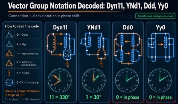
Put a delta on one side and a wye on the other and the two line voltage sets cannot line up. The delta’s line voltage is a coil voltage; the wye’s is the vector difference of two coil voltages 120 degrees apart. Taking that difference rotates the result by 30 degrees. You can wire the unit to put the low side 30 degrees ahead or 30 degrees behind, which is the difference between clock position 1 and clock position 11, and that is the only choice you have. There is no version of a delta-wye transformer with zero displacement.
Delta-delta is different. Both sides are deltas, the geometry matches, and the displacement is zero on a Dd0. Reverse the secondary winding polarity and you get 180 degrees, which is a Dd6. Those are the only two useful answers.
That single fact decides more projects than the neutral argument does, because a 30 degree unit and a 0 degree unit cannot be operated in parallel, ever, at any load, no matter how well the voltages match.
Why one neutral holds and the other wanders
A neutral is only as good as the impedance behind it. That impedance is the one number separating a delta-wye from every other connection in this discussion, and it is worth naming before it gets used.
On a delta-wye unit the primary delta is a closed loop, so zero sequence current has somewhere to go. It circulates in the triangle, produces ampere turns that oppose the load, and what the secondary sees is close to the nameplate short circuit impedance, five or six percent.
On a wye-wye unit without a delta tertiary there is no closed loop and no grounded primary neutral, so the only path left is the magnetizing branch. That impedance runs about ten times higher.
| Connection | Zero sequence path | Zero sequence impedance | What the neutral does under unbalanced load |
|---|---|---|---|
| Delta-wye | Closed loop in the primary delta | About equal to nameplate impedance, 5 to 6 percent | Holds within a few percent of nominal |
| Wye-wye, primary neutral ungrounded | Magnetizing branch only | Ten times nameplate or more | Wanders, phase voltages split apart |
| Wye-wye, primary neutral grounded | Through the utility neutral | Depends on the utility system | Holds, but exports the zero sequence to the grid |
| Delta-delta | Not applicable, no neutral brought out | Not applicable | No neutral to hold |
Ten times is not a rounding difference. It is the difference between a neutral that holds and a neutral that lets the phase voltages split, and it is why the arithmetic in the next section can use the nameplate impedance without a correction factor. It also explains why “grounded neutral” on a delta-wye means what most people assume it means, while the same phrase on a wye-wye comes with an asterisk.
A delta-wye does not have a better neutral because it has a neutral. It has a better neutral because the primary gives zero sequence current somewhere to go. Take the delta away and the same wye wanders by ten times as much.
Neutral shift, the number that decides more than topology
A grounded neutral does not mean the neutral is perfect. Any unbalanced line-to-neutral current has to return through the neutral, and the voltage drop that current produces across the transformer’s zero sequence impedance shows up as a shift of the star point. One phase goes up, another goes down, and the amount is set by two numbers: how much unbalanced current there is, and what the impedance is.
In per unit terms the relationship is short enough to do on a napkin. The neutral shift, as a fraction of nominal phase voltage, equals the neutral current in per unit times the zero sequence impedance in per unit. For a delta-wye unit the zero sequence impedance is close enough to the nameplate impedance that you can use the nameplate value.
So take a 300 kVA, 480 delta to 208Y/120 unit at 5.75 percent impedance. Rated secondary line current is 832.7 amps. Run the arithmetic across a range of unbalanced currents:
| Neutral current, percent of rated | Neutral current, amps | Neutral shift | 120 V rail becomes | Verdict |
|---|---|---|---|---|
| 25 | 208 | 1.44 percent | 118.3 and 121.7 V | Comfortable |
| 50 | 416 | 2.88 percent | 116.5 and 123.5 V | Still inside the service band |
| 52.2 | 434 | 3.00 percent | 116.4 and 123.6 V | The usual engineering limit |
| 75 | 625 | 4.31 percent | 114.8 and 125.2 V | At the edge of ANSI C84.1 Range A |
| 100 | 833 | 5.75 percent | 113.1 and 126.9 V | Out of band, motors unhappy |
This is where most of the confusion lives. People read “delta-wye gives you a neutral” and stop, as if the neutral were a bottomless source of single phase power. It is not. It is a neutral with a finite stiffness, and the stiffness is the impedance.
Three limits, not one
There are three different thresholds in play and they get quoted interchangeably, which is how a design ends up justified with the wrong number.
NEMA MG 1 treats one percent voltage unbalance as the point where motor heating starts to matter and three percent as the point where you should not keep running. ANSI C84.1 Range A sets the service voltage band at plus or minus five percent. Those are three separate tests, and the tightest one governs.
| Governing limit | Source | Unbalance allowed | Neutral current allowed, 5.75 percent Z | 120 V load allowed on a 300 kVA unit |
|---|---|---|---|---|
| Motor heating onset | NEMA MG 1, 1 percent | 1.0 percent | 17.4 percent of rated, 145 A | 17.4 kVA if all on one phase |
| Do not operate | NEMA MG 1, 3 percent | 3.0 percent | 52.2 percent of rated, 434 A | 52.1 kVA if all on one phase |
| Service voltage band | ANSI C84.1 Range A | 5.0 percent | 87.0 percent of rated, 724 A | 86.9 kVA if all on one phase |
If the facility has motors, and most do, the one percent line is the one that applies, and on a 5.75 percent unit that means a neutral current of about 17 percent of nameplate.
The 15 to 20 percent rule of thumb finally makes sense
Every old electrical handbook says to keep single phase load under 15 to 20 percent of the transformer rating. Nobody explains where the number comes from, so it gets treated as folklore and ignored.
Divide one percent by the impedance. On a 6.5 percent unit you get 15.4 percent. On a 5.75 percent unit you get 17.4. On a 5 percent unit you get 20. That is the entire rule. The folklore number is one percent of voltage unbalance divided by the impedance range that low voltage dry type transformers actually occupy.
| Transformer impedance | Single phase share that keeps unbalance at 1 percent |
|---|---|
| 2.5 percent | 40.0 percent of kVA |
| 3.5 percent | 28.6 percent of kVA |
| 4.0 percent | 25.0 percent of kVA |
| 5.0 percent | 20.0 percent of kVA |
| 5.75 percent | 17.4 percent of kVA |
| 6.5 percent | 15.4 percent of kVA |
A low impedance unit tolerates more single phase load. That is the real reason large transformers seem to handle mixed loads better than small ones, and it has nothing to do with size. It is the impedance.
The part that catches people at 80 percent loading
Here is the piece that turns this from arithmetic into a design constraint. The unbalanced current has to fit in the capacity you have not already used.
At 80 percent average loading, which is where a lot of well designed facilities sit, only 20 percent of the current capability is left over. Run that through a 5.75 percent unit and the neutral shift is 1.15 percent, which is already past the one percent motor line before you have served a single amp of unbalanced load. Add any real single phase load on top and the motors see more than one percent unbalance.
| Average loading | Spare capacity | Neutral current available | Resulting unbalance |
|---|---|---|---|
| 0 percent | 100 percent | 833 A | 5.75 percent |
| 50 percent | 50 percent | 416 A | 2.88 percent |
| 80 percent | 20 percent | 167 A | 1.15 percent |
| 95 percent | 5 percent | 42 A | 0.29 percent |
The reading is not that delta-wye is bad. The reading is that at high loading you must spread the single phase load across all three phases, deliberately, with a panel schedule that shows it, rather than letting the electrician land whatever fits. On a unit loaded past 80 percent, a delta-wye with all the 120 V load on one phase is worse than a delta-delta with a small dedicated single phase transformer, and that is a sentence you will not find in a selection chart.
Conductor amps per kVA, what the neutral really costs
The unit price gap between the two connections is small. The conductor gap is not, and it runs the other way.
Take 300 kVA and compare the secondary side on a per kVA basis, counting the neutral at full ampacity because that is what triplen load requires.
| Secondary | Line current | Conductors | Total conductor amps | Amps per kVA |
|---|---|---|---|---|
| 208Y/120, four wire | 832.7 A | 3 phase plus 1 neutral at 100 percent | 3,331 A | 11.10 |
| 240 delta, three wire | 721.7 A | 3 phase, no neutral | 2,165 A | 7.22 |
Delta-wye needs 53.8 percent more conductor amps per kVA of delivered capacity. Some of that is the neutral and some of it is the lower voltage, but the total is the total, and it shows up in copper, in conduit fill, in lug size and in the width of the wireway.
Counting the neutral at 100 percent is not pessimism. It is the code. Where the load produces triplen harmonics, the neutral carries the arithmetic sum of the three phase currents at those frequencies rather than their vector sum, and the familiar allowance to size a neutral at 70 percent of the phase conductor does not apply. Push 70 percent third harmonic on each phase and the neutral carries 210 percent of the fundamental phase current. That is why modern practice on any panel with a lot of switch mode power supplies is a full size neutral and often a double neutral.
| Third harmonic per phase | Neutral current, per unit of phase current |
|---|---|
| 33 percent | 0.99 |
| 60 percent | 1.80 |
| 70 percent | 2.10 |
The delta-delta secondary avoids this entire conversation. Three wires, no neutral, no harmonic current to add up, no 210 percent. If your load is motors and nothing else, that is a genuine simplification and it is worth money.
Where delta-delta is still the right answer
Four situations still justify delta-delta, and all four are narrower than the internet suggests.
Pure three-wire motor load, honestly assessed
If the secondary feeds motor control centers, resistance heaters, welders, rectifiers, and nothing with a line-to-neutral connection, delta-delta does the job with three wires and no neutral to maintain. The test is not what the facility does, it is what the secondary actually connects to. A plant full of motors that also has one 120 V convenience receptacle in the MCC room fails the literal test, and a small single phase transformer on that one receptacle is still cheaper than switching the whole secondary to delta-wye. The calculation flips once the 120 V load is a real panel with a lighting schedule rather than a receptacle.
Open delta as a capacity step, not a rescue
The open-delta fallback gets oversold as an emergency measure and undersold as a growth path.
A three unit delta-delta bank delivers three times the single unit rating. Remove one unit and the remaining two in open delta deliver 1.732 times the single unit rating, which is 57.7 percent of the bank. Put the third unit back and you recover the remaining 42.3 percent, which is a 73.2 percent increase over the two unit state.
That is a useful property. You can build a bank with two units sized for today, and add the third when the load arrives, with no change to the switchgear, the protection or the voltage. A single delta-wye unit has no equivalent intermediate step, because half a transformer is not a thing.
| Configuration | Capacity | Relative to one unit | What you gain |
|---|---|---|---|
| Two units, open delta | 1.732 times unit | 173 percent | A working three phase supply at 57.7 percent of a full bank |
| Three units, closed delta | 3 times unit | 300 percent | 73.2 percent more than open delta |
| One delta-wye unit | 1 times unit | 100 percent | Nothing to add later except a second transformer |
One caution that gets buried. In open delta each of the two remaining units carries its full rated current, so the 57.7 percent is a statement about capacity, not about margin. Operating a V-V bank at its nominal 57.7 percent with one unit already running hot, or with voltage unbalance from an unequal load, will shorten the life of the two survivors. Many plants run a V-V bank at about 50 percent of the original bank rating to keep some margin, and that is a reasonable habit.
Harmonic isolation and the twelve-pulse case
A delta-delta unit is a decent harmonic barrier between a dirty load and a clean bus, because neither winding passes zero sequence and the leakage impedance attenuates the rest. Where the load is a rectifier bank, that is worth having.
The version of this argument that decides a purchase order is narrower. A twelve-pulse front end is normally built as one three winding transformer with a delta and a wye secondary, and that is a single unit with one primary. If you already own a delta-delta and you are adding rectifier load, the cheaper route is a second unit with the opposite displacement and a shared primary bus, which gets you the same cancellation without replacing the transformer you have.
Two independent units, one Dd0 and one Dyn1, off the same primary bus give the 5th and 7th harmonics a 180 degree relationship at the primary, so they cancel. Ideally the 5th is 20 percent of fundamental and the 7th is 14.3 percent, and their combined amplitude of 24.6 percent drops out of the utility side, leaving the 11th at 9.1 percent and the 13th at 7.7 percent to carry the distortion.
| Harmonic order | Ideal amplitude, percent of fundamental | Present on the primary with two six-pulse bridges 30 degrees apart |
|---|---|---|
| 5 | 20.0 | Cancelled |
| 7 | 14.3 | Cancelled |
| 11 | 9.1 | Present |
| 13 | 7.7 | Present |
| 17 | 5.9 | Cancelled |
| 19 | 5.3 | Cancelled |
So there is one legitimate reason to own both a delta-delta and a delta-wye on the same facility: you want 30 degrees between them for harmonic cancellation, not parallel capacity. They still cannot be paralleled. They can share a primary bus and feed separate loads, and that is the arrangement a retrofit twelve-pulse front end is built on.
Legacy 240 V high-leg replacement
Older North American plants run 240 V center tapped delta, which gives 240 V three phase plus 120 V single phase from one bank, with the high leg at 207.8 V to neutral and marked orange for exactly that reason.
What matters for the decision is the replacement path. If you are replacing a high-leg bank in kind, you stay with delta-delta, because the panelboards, the breaker positions and the 120 V circuits are all built around that arrangement. Converting to 208Y/120 means new panelboards, new breakers, and a survey of every 240 V load that suddenly gets 208 V instead. That is a 13.3 percent voltage drop, and on a motor it costs about 25 percent of breakdown torque, which is enough to stop a loaded conveyor from starting. The transformer is the cheap part of that project.
| Reading | 240 V high-leg delta | 208Y/120 wye |
|---|---|---|
| Phase to phase | 240 V | 208 V |
| Normal leg to neutral | 120 V | 120 V |
| High leg to neutral | 207.8 V | Not applicable |
| Phase to ground, all three | 120, 120, 208 V | 120 V |
| Motor terminal voltage | 240 V | 208 V, which is a 13.3 percent drop |
That last row is the reason conversions get abandoned halfway. A 240 V motor on a 208 V supply loses torque proportional to voltage squared, about 25 percent of breakdown torque, and many of them will not start a loaded conveyor.
Where delta-wye is not a preference
Now the other direction, where the choice is made for you.
Any 120 V or 277 V load at all
The moment a single line-to-neutral circuit exists on the secondary, delta-delta is out unless you add a transformer. That is not a code opinion, it is a wiring fact. There is no point in a delta secondary at the electrical center of a phase, so there is no 120 V to be had.
This is also where 480Y/277 comes in. A 480 V wye secondary gives 277 V line to neutral, which is the standard voltage for commercial lighting and for a lot of rooftop equipment. If your distribution is 480Y/277, the service transformer is almost always delta-wye, because the Y is the only way to get the 277 out.
Four-wire service and the separately derived system
A transformer secondary is a separately derived system, and a separately derived system with a grounded conductor has grounding and bonding rules of its own. The secondary neutral gets bonded to the equipment grounding conductor at the transformer, a grounding electrode conductor runs to the building’s electrode system, and from that point on the neutral and the equipment ground are separate everywhere downstream.
None of that machinery exists on a delta-delta secondary with no neutral. You still bond the enclosure and the equipment ground, but there is no system grounded conductor, so there is no neutral to bond and no neutral to switch. That simplifies the grounding, and it also means an ungrounded 480 V delta needs ground fault detection, which is the subject of a later section.
Unbalanced single phase load and the neutral that has to carry it
This is where delta-wye earns its keep and where the unbalance limit from earlier decides whether it works.
A delta-wye lets you spread single phase load across three branches. Thirty kVA of 120 V load becomes 10 kVA per phase, roughly 83 A per leg, and the three currents are nearly balanced, so almost no negative sequence is produced. The same 30 kVA hung across one pair of lines on a 240 V delta, which is the delta-delta counterpart at the same kVA, produces 125 A in that one winding, a positive and negative sequence component of 72 A each, which is 10 percent of that unit’s line rating and 0.575 percent voltage unbalance. The comparison is per unit, so the two voltages do not have to match for the arithmetic to hold.
| Single phase load | On a delta-wye, spread over three branches | On a delta-delta, across one pair of lines |
|---|---|---|
| 30 kVA | 83 A per leg, unbalance near zero | 125 A in one winding, 0.58 percent unbalance |
| 60 kVA | 167 A per leg, unbalance near zero | 250 A in one winding, 1.15 percent unbalance |
| 100 kVA | 278 A per leg, unbalance near zero | 417 A in one winding, 1.92 percent unbalance |
The negative sequence is not a property of the load. It is a property of whether the connection gives you a place to spread that load. That is the whole argument, and it is worth stating plainly because the usual phrasing, “delta-wye handles unbalanced load better,” does not tell you why or by how much.
What each connection does to the harmonic picture
The harmonic story is more symmetrical than the marketing suggests, and the asymmetry that does exist is in the voltage, not the current.
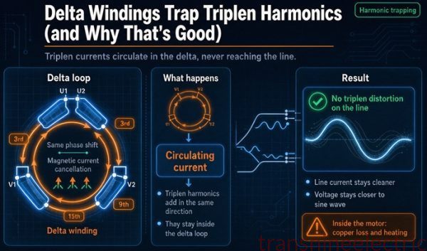
Both connections trap triplen current. On a delta-wye, the load’s third harmonic current circulates in the primary delta. On a delta-delta, it circulates in the secondary delta as well, so the primary never sees it either. On triplen current, a tie.
| Connection | Triplen current from the load | Triplen voltage on the secondary | Where it shows up |
|---|---|---|---|
| Delta-wye | Circulates in the primary delta | Present in phase voltage, absent in line voltage | A 120 V leg with a few percent distortion that a 208 V meter will not read |
| Delta-delta | Circulates in the secondary delta, then the primary | Absent, because phase voltage is line voltage | Nowhere on the secondary |
| Wye-wye, no tertiary | Passes to the utility | Present in both | Utility feeder and every downstream load |
| Wye-wye with delta tertiary | Circulates in the tertiary | Reduced | The tertiary has to be rated for it |
If your load is single phase rectifiers on a 240 V delta and the waveform quality matters to you, delta-delta is the better answer. If your load is motors and you need 277 V lighting, the phase voltage distortion on a delta-wye is real but usually small enough to ignore, and the neutral is worth more than the distortion costs.
One habit worth having. On a delta-wye unit feeding a panel with a lot of switch mode supplies, put a meter on phase to neutral and look at the waveform, not just the RMS. The RMS number can look fine while the flat topping is doing work on every capacitor in the building.
Ground fault behavior, and the 480 V trap
This is the section where the two connections differ most, and where the difference gets described badly.
Delta-delta rides through a single ground fault
An ungrounded delta has no intentional connection between any phase and earth. The only coupling is the distributed capacitance of the cable and the windings, which is small. A single phase to ground fault completes a circuit through that capacitance and produces a charging current measured in amps, usually under three on a medium sized plant. Nothing trips. Production continues. That is the entire reason ungrounded delta survives in melting furnaces, drive systems and continuous process lines.
The cost is the voltage. Before the fault, each phase sits at 277 V to ground on a 480 V system, because the capacitance divider puts the system near the wye equivalent neutral. After one phase goes solidly to ground, the other two sit at 480 V to ground. That is a 73.2 percent rise, and it is a permanent condition until somebody finds the fault.
| System state | Phase A to ground | Phase B to ground | Phase C to ground |
|---|---|---|---|
| Healthy, 480 V ungrounded delta | 277 V | 277 V | 277 V |
| Phase A solidly grounded | 0 V | 480 V | 480 V |
| Second fault on phase B | 0 V | 0 V | Phase to phase, low impedance |
That second row is why the code does not let you run ungrounded and forget about it. NEC 250.21(B) makes ground detectors a condition of operating ungrounded in this voltage range, with sensing equipment located as close as practicable to the supply. NEC 250.21(C) requires a durable marking at the source or at the first disconnecting means, reading “Caution: Ungrounded System Operating, ___ Volts Between Conductors.” Article 408 puts the same field marking on the switchboard or panelboard.
The other half of the requirement is human. The exception for ungrounded operation assumes trained personnel monitoring the detector and holding the authority to de-energize. A plant that installs the detector and ignores the alarm has the hazard without the protection.
There is a third option worth knowing about. A high resistance grounded system, permitted for 480 V to 1000 V three phase systems under conditions that include qualified maintenance and continuous ground detection and no line-to-neutral loads, limits the fault current to a few amps and alarms without tripping. It gives you the continuity of an ungrounded system with a defined voltage reference. It is not a delta-wye and it is not a plain delta-delta, and it is often the right answer for a plant that wants both.
Delta-wye clears the fault and tells you where it is
On a solidly grounded wye secondary, a phase to ground fault is a short circuit through the neutral bond, and the overcurrent device clears it. That is safer for people and much easier to troubleshoot, and it is the main reason modern facilities are grounded.
The trade is continuity. A ground fault on a delta-wye secondary is an outage, and in a continuous process that outage can cost more than the fault.
For a buyer, the practical version of this section is short. Ask two questions. Does the process need to ride through a single ground fault? If yes, you are looking at an ungrounded or high resistance grounded delta, and you are also accepting the detector, the marking and the training. If no, ground the neutral and move on.
Phase shift, paralleling, and the twelve-pulse exception
Two transformers can be operated in parallel only if their voltage ratios match, their impedances are reasonably close, their polarity and phase sequence match, and their phase displacement is identical or differs by a multiple of 120 degrees that you can fix by rolling phases. That last condition is where delta-wye and delta-delta part company.
| Vector group | Displacement | Can parallel with Dd0 | Can parallel with Dyn1 |
|---|---|---|---|
| Dd0 | 0 degrees | Yes | No, 30 degrees apart |
| Dd6 | 180 degrees | No, unless phases rolled | No |
| Dyn1 | 30 degrees, low side lagging | No | Yes, with another Dyn1 |
| Dyn11 | 330 degrees, low side leading | No | No, 60 degrees apart |
The Dyn1 versus Dyn11 distinction is worth a sentence because it surprises people. Both are delta-wye. Both have 30 degrees of displacement. They are 60 degrees apart from each other, because one lags by 30 and the other leads by 30, and 60 degrees is not a multiple of 120, so they cannot be paralleled either. Two delta-wye transformers from different suppliers can be just as incompatible as a delta-wye and a delta-delta.
Circulating current at 30 degrees
The current that flows when you close a tie between two units 30 degrees apart is large enough that the arithmetic is worth doing before the switch is installed rather than after.
The relationship is the voltage difference between the two sources divided by the sum of the two impedances. At 30 degrees, with two 5.75 percent units, it comes to 4.5 times rated current. That figure is easy to find in any treatment of the subject. What is less often carried through is what it means at a given kVA, and how fast it gets worse at larger angles.
| Displacement | Numerator, 2 sin of half angle | Circulating current, two 5.75 percent units | On a 1,500 kVA 480 V pair |
|---|---|---|---|
| 30 degrees | 0.5176 | 4.50 per unit | 8,121 A |
| 60 degrees | 1.0000 | 8.70 per unit | 15,692 A |
| 180 degrees | 2.0000 | 17.39 per unit | 31,378 A |
A 1,500 kVA unit at 480 V carries 1,804 A at nameplate. The 30 degree mismatch drives 8,121 A through the pair before either one picks up any load, which is 4.5 times nameplate and roughly half of what a bolted fault at the secondary terminals would produce. Both overcurrent devices trip, or neither does and the windings cook.
Note the 180 degree row. At 180 degrees the circulating current is exactly twice the reciprocal of the impedance sum, which is precisely the bolted fault current of one unit. A Dd0 and a Dd6 closed together are not a mismatch, they are a fault.
Closed transition, ATS poles, and the neutral
A transfer switch that breaks before it makes does not care about phase displacement, because the load is dead during the transfer. A closed transition switch, the kind that parallels the two sources for a fraction of a second to avoid dropping the load, cares very much. If the two sources are 30 degrees apart, closed transition is not available, and that removes an option people assume they have.
The neutral adds a second decision. A three pole transfer switch leaves the neutral solid from the utility to the load, which means the generator’s neutral and the utility’s neutral are connected together whenever the generator is running. That creates a parallel neutral path and, on a separately derived generator, an improper bond. A four pole switch breaks the neutral and treats the generator as a separately derived system, which is correct but requires the neutral to be switched, sized and bonded properly at both ends.
| Transfer arrangement | Neutral behavior | Works with delta-wye | Works with delta-delta |
|---|---|---|---|
| Three pole, break before make | Neutral continuous | Yes, if the generator is not separately derived | Yes, no neutral to switch |
| Four pole, break before make | Neutral switched | Yes, the correct arrangement for a separately derived source | Not applicable, no neutral |
| Three pole, closed transition | Neutral continuous | Only if both sources are the same vector group | Only if both are Dd0 |
The neutral question is another place where the delta-delta looks simpler. There is nothing to switch, nothing to bond twice, and no circulating neutral current between two sources. If the facility is a motor plant with its own generation, that simplicity is real.
The cost side, priced honestly
Quotes make this look like a 5 percent decision. It is a 5 percent decision on the transformer and a much bigger one on everything attached to it.
The unit itself
A delta-delta saves one X0 bushing and the neutral bus inside the tank or the enclosure. At 300 to 500 kVA that shows up as roughly 3 to 7 percent of the transformer price. It is not nothing, and it is not the reason to pick a connection.
What the neutral costs downstream
The 53.8 percent conductor figure from earlier is the real line item. On a 300 kVA unit, the delta-wye secondary asks for 3,331 conductor amps against 2,165 for the delta-delta, and that difference compounds through conduit, wireway, lugs, terminal blocks and the physical size of the section.
The second transformer nobody budgets
Flip the case. A facility that chose delta-delta for a 240 V motor load and then adds 120 V receptacles has to buy a single phase transformer, a feeder, a breaker, a disconnect, wall space, and a second grounding electrode conductor run. That package usually costs more than the delta-wye unit would have cost in the first place, and it is bought under time pressure after the need appears.
Ground fault detection, the delta-delta tax
An ungrounded delta needs detection and marking. A three lamp detector is cheap. A modern insulation monitoring relay with communications and a remote annunciator is not, and neither is the labor to commission it or the training to make the alarm mean something. Add the periodic testing that keeps the detector honest.
| Cost item | Delta-wye | Delta-delta |
|---|---|---|
| Transformer unit, same kVA | Baseline | 3 to 7 percent lower |
| Secondary conductors per kVA | 11.1 amps | 7.2 amps |
| Neutral bus and terminations | Included | Not present |
| Ground fault detection | Not required, neutral is grounded | Required, plus marking |
| Small 120 V load | Serve it from the panel | Add a single phase transformer and its feeder |
| Transfer switch | Four pole if the source is separately derived | Three pole is enough |
| Parallel operation with an existing unit | Only with a matching vector group | Only with a matching vector group |
Read the table down the columns rather than across the rows. Delta-wye wins on the small load and loses on the conductors. Delta-delta wins on the conductors and loses on the detection and the second transformer. Neither column is shorter, which is why the decision has to come from the load rather than from the price.
A worked example, 300 kVA, two ways
An actual facility decision, with the numbers.
The load is a machine shop. Connected load is 240 kVA of three phase motors, 25 kVA of 480 V process heat, 30 kVA of 120 V convenience and lighting load distributed across the shop, and 15 kVA of single phase load for a welder and a compressor, nameplated 208/240 V so it can run on either secondary. Demand factor puts the peak near 250 kVA, which is a bit over 80 percent of a 300 kVA unit.
Option one, 480 delta to 208Y/120, delta-wye, 5.75 percent.
The 30 kVA of 120 V load goes to ten kVA per phase if the panel schedule is done properly, which is 83 A per leg and a neutral current near zero. The 15 kVA welder goes line to line at 208 V, which is 72 A in the two loaded lines and about 42 A of negative sequence. That negative sequence lands near five percent of rated and produces just under 0.3 percent voltage unbalance, and the neutral shift from the 120 V load is close to zero because the load is spread evenly. The 240 kVA of motors runs at 208 V, so every motor has to be rated 208 V or be replaced, because a 240 V motor on 208 V loses about 25 percent of its breakdown torque.
Option two, 480 delta to 240 delta, delta-delta, 5.75 percent.
The motors get 240 V, which is what they were bought for. The 30 kVA of 120 V load cannot be served, so a 37.5 kVA single phase transformer goes in at 240 to 120/240, plus a feeder and a breaker. The 15 kVA welder lands across one pair of lines at 240 V, which puts 62.5 A in one winding and produces 0.29 percent unbalance, which is fine. The three phase capacity used is the same, and the secondary is three wires instead of four.
| Item | Option one, delta-wye | Option two, delta-delta |
|---|---|---|
| Transformer | 300 kVA, 480D to 208Y/120, Dyn1, 5.75 percent | 300 kVA, 480D to 240D, Dd0, 5.75 percent |
| Secondary conductors | 4 runs, 833 A each, 3,331 conductor amps | 3 runs, 722 A each, 2,165 conductor amps |
| Motor terminal voltage | 208 V | 240 V |
| Motor torque available | 75 percent of nameplate breakdown | 100 percent |
| 120 V load | Served from the main panel | Needs a 37.5 kVA single phase transformer |
| Ground fault detection | Not required | Required, with marking |
| Voltage unbalance at this load | Under 0.3 percent | 0.29 percent |
| Parallel with a future unit | Needs another Dyn1 | Needs another Dd0 |
On this load the delta-delta wins, and it wins for a reason that has nothing to do with the transformer. The motors are 240 V. Choosing delta-wye means either replacing the motors or accepting a 25 percent torque loss, and neither is a transformer decision.
Change one line of the brief and the answer flips. If the same shop had 480 V motors and 277 V lighting, the delta-wye would win without a contest, because 277 V does not exist on a delta.
That is the shape of every real decision on this question. The connection follows the load voltage, and the load voltage is usually already fixed by equipment that was bought years ago.
What to put on the RFQ when the connection is the question
Most of the bad outcomes in this decision are specification failures rather than engineering failures. A purchase order that says “300 kVA delta-wye transformer” will produce a unit, and it may well be the wrong unit.
A transformer requisition carries a lot of generic fields, and the generic ones are well documented. These are the nine that decide which connection you get, and they are the ones most often left to the supplier to fill in.
| Field | What to write | Why it decides the connection |
|---|---|---|
| Primary voltage and connection | 480 V, 3 phase, 3 wire, delta | A wye primary on a three wire feeder is a change order |
| Secondary voltage and connection | 208Y/120 V, 3 phase, 4 wire | The Y is what produces the neutral |
| Vector group | Dyn1 for North America, Dyn11 for IEC practice | Decides what it can parallel with, forever |
| kVA | 300, or the next standard size up | The ladder is 225, 300, 500, not any number you like |
| Impedance | 5.75 percent, and state the tolerance | Sets both the unbalance limit and the fault current |
| Tap range | Two above, two below, 2.5 percent each | Voltage adjustment you cannot add later |
| Neutral | X0 brought out and fully rated, or 200 percent | The single most skipped line on the page |
| Harmonic duty | K rated, or state the non-linear load share | Decides whether a standard unit survives the load |
| Grounding | Solidly grounded at X0, or ungrounded with detection | Decides the detector, the marking and the training |
The neutral rating deserves its own paragraph. A delta-wye transformer with a neutral brought out but sized at 50 percent of the phase conductor will overheat its neutral bus on a harmonic rich load, and it will do so quietly for years. Specify it at 100 percent, or 200 percent if the load is mostly electronics, and put the number on the drawing rather than in a footnote.
Two more lines that pay for themselves. Ask for the impedance tolerance as a percentage, not just a nominal value, because a unit that comes in at 5.2 percent instead of 5.75 changes both your fault current and your unbalance limit. And ask for the connection diagram and the nameplate photograph before shipment, because the vector group on that drawing is the only thing that tells you what you can parallel with later.
If you are working through a decision like the one in the worked example and want a second read on the vector group against the load schedule, start here and send the single line and the panel schedule. The useful answer needs the load voltages, the existing transformer’s vector group if there is one, and whether anything in the plant has to ride through a ground fault. Everything else is detail.
The decision, in order
Work down this list and stop at the first line that applies. It resolves almost every case in four questions.
- Does anything on the secondary need line to neutral voltage? If yes, delta-wye, and the rest is sizing.
- Is there an existing transformer this one must parallel or transfer with? If yes, match its vector group exactly, including the clock number.
- Does the process have to ride through a single ground fault? If yes, ungrounded delta with detection, or a high resistance grounded system, and accept the detector, the marking and the training.
- Is the load pure three wire, and is the open-delta growth path worth something to you? If yes, delta-delta.
- None of the above applies cleanly. Take the delta-wye, because it keeps more doors open and the price difference is a few percent.
The order matters. Most people start at question four, because delta-delta is the interesting answer, and then discover at commissioning that question one was true all along.
One last check that catches more errors than any calculation. Before you order, walk the secondary and write down every voltage that will be connected to it. Not the categories, the actual nameplate voltages. If a 120 appears anywhere on that list, the delta-delta is gone and the conversation is over. If a 277 appears, it was never a conversation.
FAQ
Is delta-wye always better than delta-delta?
No. Delta-wye is more common because most facilities have a line-to-neutral load, not because it is better. On a pure three wire motor load, delta-delta gives you three conductors instead of four, a 3 to 7 percent lower unit price, and an open-delta growth path that a single delta-wye unit cannot match. The connection should follow the load, and on about a quarter of industrial loads the load points at delta-delta.
Can a delta-delta transformer supply 120 V?
Not from the transformer itself. A delta secondary has no point at the electrical center of a phase, so there is no line-to-neutral voltage to bring out. You can get 120 V two ways. Add a single phase transformer fed from two of the three phases, the usual answer for a small load. Or specify a center tapped delta, giving 120 V on two legs and 207.8 V on the high leg, marked orange and never used for a 120 V circuit.
What is the 30 degree phase shift and why does it matter?
A delta’s line voltage is a coil voltage and a wye’s is the vector difference of two coil voltages 120 degrees apart, so a delta on one side and a wye on the other rotates the output by 30 degrees. It matters because two units 30 degrees apart cannot be paralleled. Closing a tie between them drives 4.5 per unit of circulating current with 5.75 percent units, which is 8,121 A on a 1,500 kVA 480 V pair.
Why can’t a Dyn1 and a Dyn11 be paralleled?
Both are delta-wye and both have 30 degrees of displacement, but one puts the low side 30 degrees behind the high side and the other puts it 30 degrees ahead. That is 60 degrees between them, and 60 is not a multiple of 120, so the phase relationship cannot be fixed by rolling phases. Two delta-wye transformers from two suppliers can be just as incompatible as a delta-wye and a delta-delta.
What happens to the voltage when one phase of an ungrounded delta goes to ground?
Nothing trips, and the other two phases rise from 277 V to 480 V to ground on a 480 V system. That is a 73.2 percent increase, and it stays until the fault is found. The system keeps running, which is the point, and every cable, motor winding and surge arrester on those two phases is now seeing full line voltage to ground instead of 58 percent of it.
Is an ungrounded delta legal?
Yes, under NEC 250.21, but not unconditionally. The system needs ground detectors that give a visual indication, trained personnel who monitor them and have the authority to de-energize, and assurance that the continuity of the ungrounded system is maintained. NEC 250.21(C) also requires a durable marking at the source or first disconnecting means, and Article 408 puts the same marking on the switchboard.
How much single phase load can a delta-wye carry?
The limit is set by neutral shift, not by the transformer rating. Neutral shift as a fraction of phase voltage equals the neutral current in per unit times the impedance in per unit, so the allowed single phase share is the target unbalance divided by the impedance. At one percent unbalance on a 5.75 percent unit that is 17.4 percent of kVA. At three percent it is 52.2 percent.
Why does the 15 to 20 percent rule exist?
It is one percent voltage unbalance divided by the impedance range of low voltage dry type transformers. One divided by 6.5 percent is 15.4. One divided by 5.75 is 17.4. One divided by 5 is 20. The rule is arithmetic on the hardware, not a convention, which is why it moves when the impedance moves.
Does delta-wye trap harmonics?
It traps triplen harmonic current, not voltage. That current circulates in the primary delta and never reaches the utility. Less known is that the wye secondary has no zero sequence path, so that voltage stays on the phase voltage. Line voltage is clean because the harmonic is common to all three. Phase voltage is not, and on a 208Y/120 unit a 120 V leg can carry distortion a 208 V meter will never show.
What is the capacity of an open delta bank?
Two units in open delta deliver 1.732 times one unit, which is 57.7 percent of a three unit bank. Each of the two units runs at its full rated current at that capacity, so 57.7 percent is a capacity statement with no margin in it. Many plants run a V-V bank at about 50 percent of the three unit rating to keep some margin, especially if the load is unbalanced.
How much does delta-delta save?
On the transformer alone, roughly 3 to 7 percent at 300 to 500 kVA, because it saves one X0 bushing and the internal neutral bus. On the installed cost it can go either way. Delta-delta needs three secondary conductors instead of four, which is 7.2 amps per kVA instead of 11.1, but an ungrounded delta also needs ground fault detection, marking, and often a second single phase transformer for the 120 V load that turns up later.
What is a high leg and why is it orange?
On a 240 V center tapped delta, one winding is center tapped to give 120 V on two legs. The third leg sits at 207.8 V to neutral, which is 240 times the cosine of 30 degrees, and it is the high leg. It must be identified with orange at every termination under NEC 110.15 and 230.56, and the high leg must be the B phase in switchboards and panelboards. Connecting a 120 V circuit to it puts 208 V across a 120 V load.