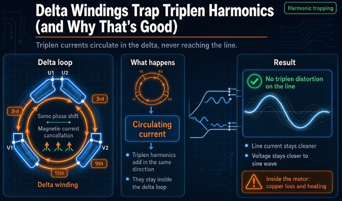
A delta does not filter the third harmonic. It gives that current a closed loop, the ampere turns cancel, and the flux never sees it. Voltage stays sinusoidal and the distortion never reaches the utility lines. That is why almost every 480 to 208Y/120 unit is delta-wye. The catch is the heat, and nobody quotes it.
That last sentence is the whole article. The mechanism is well documented and I am not going to pretend otherwise. What is missing from nearly every page on this subject is the accounting: how many amps actually circulate, what they cost in watts, and which of your three numbers (THD, K factor, neutral size) is the one that is actually wrong.
What “trap” really means
Start with the geometry, because the word trap is doing a lot of unearned work.
In a balanced three-phase system, the fundamental currents are 120 degrees apart. They sum to zero. Any harmonic whose order is a multiple of three does not behave that way. Take the third harmonic. If phase B lags phase A by 120 degrees at the fundamental, its third harmonic lags by three times 120, which is 360 degrees, which is no lag at all. Same for phase C: three times 240 is 720, also zero. So the third harmonic current in all three phases is in phase. The ninth, fifteenth, twenty-first and so on behave identically. These are the triplens.
In phase means they add. Three equal currents adding in a neutral gives you three times one of them, not zero. That is the entire neutral problem in one sentence.
The cancellation is subtraction, not suppression
Now put a delta in the path. In a delta, each line connects to the junction of two windings, so the line current is the difference between the currents in the two windings that meet there:
Ia = Iab - Ica
Ib = Ibc - Iab
Ic = Ica - Ibc
Add a common circulating component I_c to all three windings. That is what the triplen is: the same magnitude, the same phase, in all three. Then:
Ia = (Iab + I_c) - (Ica + I_c) = Iab - IcaThe I_c terms subtract out. Every time. Not because the delta absorbed anything, not because it blocked anything, but because the line current is a difference and the triplen is common mode. A difference kills a common mode exactly.
This is the honest version of the mechanism, and it has a consequence that the filter metaphor hides. Nothing was filtered. The current is still there, circulating around the closed loop, and it will keep circulating as long as the load draws it. A filter has an output that goes somewhere: a shunt path to ground, a tuned trap, a dissipative element. A delta has no output. The energy stays in the copper.
So the word trap is accurate in the sense that the current cannot leave. It is misleading in the sense that trapped things are usually inert. This one is not. It is doing I squared R in your winding right now.
Why the flux stays sinusoidal, which is the older reason
There is a second job the delta does, and it predates nonlinear loads by decades. It is the reason generator step-up transformers are delta on the machine side, and it applies even to a load that draws a perfect sine wave.
Faraday’s law says the flux in a core is the integral of the applied voltage. Apply a sine wave, get a sine wave flux. That part is not negotiable. But the current needed to produce that flux is set by the B-H curve of the steel, and that curve is not a straight line. It flattens at the top. To push a sinusoidal flux through a saturating core, you need a current that peaks hard near the zero crossings of the flux, and a peaked wave is a fundamental plus a strong third harmonic plus smaller odd harmonics above it.
For a typical distribution core, that third harmonic component of magnetizing current runs 30 to 50 percent of the fundamental magnetizing current. It is normal. It is supposed to be there. The question is whether it has somewhere to go.
Give it a delta, and it circulates. The flux stays sinusoidal, the induced voltage stays sinusoidal, and everyone downstream is happy. Take the delta away, and the current has no path, so it stays sinusoidal instead, which forces the flux to go flat-topped to satisfy the same B-H curve. A flat-topped flux is a fundamental plus a third harmonic flux, and that third harmonic flux induces a third harmonic voltage in every winding on the core.
That is the failure mode, and it is a voltage failure, not a current failure. Here is what it costs, measured as the peak of the phase-to-neutral wave:
| Third harmonic voltage | 277 V phase, peak | 120 V phase, peak |
|---|---|---|
| none | 391.7 V | 169.7 V |
| 15% | 450.5 V | 195.2 V |
| 30% | 509.3 V | 220.6 V |
| 40% | 548.4 V | 237.6 V |
| 50% | 587.6 V | 254.6 V |
| 60% | 626.8 V | 271.5 V |
The peak rises by exactly the third harmonic percentage, because the harmonic adds in phase at the crest. At 50 percent you are putting 588 volts of peak on insulation, arresters and every 120 volt power supply downstream that was selected for 392. Published figures for wye-wye units without a delta path run 15 to 60 percent depending on how hard the core is pushed, so the top of that table is not hypothetical.
The nasty part is that line-to-line voltage stays clean. Take two phase voltages that both carry the same third harmonic, subtract them, and the harmonic cancels exactly as it did in the delta. So a voltmeter across two phases reads a beautiful sine wave while every phase-to-neutral measurement is distorted. Any protection or metering fed only from phase-to-phase transformers is structurally blind to this. That is not a fringe case, it is how a lot of switchgear is wired.
Two sources of a third harmonic, two very different sizes
There are two entirely separate third harmonic currents in any transformer, and conflating them is why the topic resists a straight answer.
The first comes from the core. It exists at no load, it is a property of the steel, and it is what the delta was invented for. On a 1,000 kVA unit the no-load current is around 1.5 percent of rated, which is 18 amps. Forty percent of that as third harmonic is 7.2 amps, and that is what circulates in the delta when the transformer sits there with nothing connected to the secondary.
The second comes from the load. A floor of switch-mode supplies drawing 40 percent third harmonic on a unit loaded to rated fundamental puts 1,110 amps of third harmonic in each 208 volt phase, which reflects to 278 amps circulating in the delta. Same mechanism, same loop, roughly 39 times the current.
That ratio explains a lot of bad advice. Someone reads that generator step-up transformers are delta connected to keep the third harmonic out of the stator, which is true and is about the magnetizing component, and concludes that the delta on a 208 volt unit is handling something similar. It is not. The magnetizing third harmonic is a 7 amp problem that the delta solves completely and almost for free. The load third harmonic is a 278 amp problem that the delta also solves, and charges you 2,943 watts for the privilege, which is 25,777 kilowatt hours a year.
It also means a building with nothing but linear load still has circulating current. Small, harmless, but present. If you put a sensitive measurement on a delta winding at no load and find a few amps of 180 Hz current, that is not a fault. That is the core doing what cores do.
The number nobody quotes: what the winding actually carries
Now the accounting. Here is where the delta stops being a free lunch.
The circulating current is set by ampere turns, and the arithmetic collapses into something unusually clean. For a 1,000 kVA unit stepping 480 down to 208Y/120, the turns ratio per winding is 480 divided by 120.09, which is 3.997. The delta winding is rated 694.4 amps. The wye winding is rated 1,602.6 amps. The 480 volt lines are rated 1,202.8 amps and the 208 volt lines are rated 2,775.7 amps.
Balance the ampere turns and you get this: the circulating current in the delta, expressed in per unit of the delta winding’s own rating, equals the triplen current expressed in per unit of the load’s fundamental. A 40 percent third harmonic load puts 40 percent of rated current around the loop. That is not an approximation. It falls straight out of N1 times I1 equals N2 times I2.
| Third harmonic | Per phase on wye | Circulating in delta | % of winding rating | % of line rating | Delta winding total |
|---|---|---|---|---|---|
| 10% | 277.6 A | 69.4 A | 10.0% | 5.8% | 100.5% |
| 20% | 555.1 A | 138.9 A | 20.0% | 11.5% | 102.0% |
| 30% | 832.7 A | 208.3 A | 30.0% | 17.3% | 104.4% |
| 40% | 1,110.3 A | 277.8 A | 40.0% | 23.1% | 107.7% |
| 50% | 1,387.9 A | 347.2 A | 50.0% | 28.9% | 111.8% |
| 66.7% | 1,851.4 A | 463.2 A | 66.7% | 38.5% | 120.2% |
| 80% | 2,220.6 A | 555.6 A | 80.0% | 46.2% | 128.1% |
Read the fourth and fifth columns together. At 40 percent third harmonic, the delta winding is at 40 percent of its rating, but the 480 volt lines are only at 23 percent. The same current looks twice as big depending on which side of the terminal you measure from, because the winding rating is the line rating divided by 1.732.
Two hundred and seventy eight amps a clamp meter cannot see
Here is the operational consequence, and it is the reason this failure always gets discovered late.
Picture a 1,000 kVA delta-wye feeding a floor of switch-mode power supplies, 40 percent third harmonic, fundamental load at nameplate. The primary line current is 1,202.8 amps. That is exactly 100.0 percent of the nameplate rating. The load’s apparent power is 1,077 kVA once you count the harmonic, so the unit is being asked for 107.7 percent of nameplate, and the meter still reads a perfectly comfortable 1,202.8.
Inside the tank, the delta windings are carrying 277.8 amps of 180 Hz current on top of 694.4 amps of fundamental. The combined RMS is 747.9 amps, which is 107.7 percent of the winding rating. The load loss is up 32.7 percent. The unit is running hotter than it would at 107 percent of nameplate on a clean sine wave, and the only instrument that shows it is a thermal camera.
Worse: the 277.8 amps never appears on any conductor you can put a clamp around. It is internal to the winding. To find it you either compute it from the secondary spectrum or you measure temperature. The textbook literature makes this point in one line and moves on, which is a shame, because it is the single most useful thing to know about servicing these units. Measuring current on the delta side of a transformer does not tell you the heating the transformer is experiencing.
Where the heat actually lands
Three places. They have different owners and different fixes, which is why the problem is so often half-solved.
The delta winding
At 40 percent third harmonic the load loss goes from 1.000 to 1.327 per unit. That number depends on how much of the load loss is eddy current, which I have taken at 15 percent, a reasonable figure for a dry-type unit in this size. If the unit is mostly I squared R, the multiplier is closer to 1.16. If it has a lot of eddy loss, it goes higher:
| Eddy fraction | Load loss multiplier | Extra loss |
|---|---|---|
| 0.10 | 1.276 | 27.6% |
| 0.15 | 1.327 | 32.7% |
| 0.20 | 1.373 | 37.3% |
Translate that into watts and the “free” filtering stops being free. On a 500 kVA unit with 6,000 watts of load loss at full load, 40 percent third harmonic adds 1,962 watts. Run it 8,760 hours and that is 17,185 kWh, or about 1,718 dollars a year at ten cents. On a 1,000 kVA unit with 9,000 watts of load loss it is 2,943 watts, 25,777 kWh, roughly 2,578 dollars a year. That is the bill for the harmonics the utility never saw.
Break-even arithmetic matters here. You are paying that money to keep the primary clean. If your utility does not care, and many do not enforce IEEE 519 at a small service, you have bought a benefit for someone else. That is not an argument against delta-wye, which you were going to buy anyway for other reasons. It is an argument against telling yourself the harmonic handling is free.
The neutral
The neutral carries three times the per-phase triplen, and this is the one number almost everyone gets roughly right and precisely wrong.
Take the same 1,000 kVA at 40 percent third harmonic. Each 208 volt phase carries 1,110.3 amps of third harmonic. The neutral carries 3,330.9 amps. The phase conductors are rated 2,775.7 amps. So the neutral is at 120 percent of the phase rating while the phase conductors, including their harmonics, are at 107.7 percent.
Now size it. Copper at 75 degrees C gives 475 amps for 750 kcmil. Six sets is 2,850 amps, which covers the 2,775.7 amp phase. Seven sets is 3,325 amps, which covers 3,330.9 amps by minus six amps. It does not cover it. You need eight sets for the neutral and six for the phases, because a 5.9 amp shortfall is still a shortfall and 240.4(C) does not let you round up above 800 amps.
| Third harmonic | Neutral / phase RMS | Neutral / nameplate phase | Fits a 100% neutral? | Fits a 200% neutral? |
|---|---|---|---|---|
| 20% | 0.59 | 60% | yes | yes |
| 33.3% | 0.86 | 100% | at the limit | yes |
| 40% | 1.11 | 120% | no | yes |
| 50% | 1.34 | 150% | no | yes |
| 66.7% | 1.67 | 200% | no | at the limit |
| 70.7% | 1.73 | 212% | no | no |
| 80% | 1.87 | 240% | no | no |
That table is the reason a double neutral is a design choice and not a rule. A 200 percent neutral runs out at 66.7 percent third harmonic. Office and data hall spectra routinely land at 70 to 80. So the standard fix, “specify a 200 percent neutral,” is a fix that works up to a point and then quietly stops working, and the point is right about where modern loads live.
The neutral is a current-carrying conductor, and that costs you phase copper
Here is a second-order effect that almost never makes it onto a drawing review, and it is worth about two extra sets of conductor.
In an ordinary three-phase four-wire feeder serving balanced linear load, the neutral carries only unbalance, so the code does not make you count it as a current-carrying conductor. Three conductors, no adjustment, full ampacity. The moment the neutral is carrying triplen current, that changes. It is a current-carrying conductor now, and the ampacity adjustment in 310.15(C)(1) applies to every conductor in the raceway.
Four to six current-carrying conductors gets you 80 percent. So the same feeder, same load, same conduit goes from unadjusted to 80 percent of the table value:
| Condition | 750 kcmil ampacity | Sets needed for 2,775.7 A |
|---|---|---|
| Neutral carries unbalance only | 475 A | 6 sets |
| Neutral carries triplen, counted | 380 A | 8 sets |
Two more sets of 750 kcmil, in the same raceway, because a harmonic you were told the transformer would handle made the neutral a live conductor. If you want the arithmetic in one sentence: the delta moved the harmonic out of the lines and into the winding, and the neutral moved it back into your conduit schedule.
None of this is an argument against the connection. It is an argument for doing the harmonic calculation at the feeder sizing stage rather than after the transformer is on the dock, because the two decisions are the same decision.
The core
If you take the delta away you do not just lose a current path. On a three-legged core you also change where the triplen flux goes.
A three-legged core has no return leg for zero-sequence flux. The flux has to come back through the tank, the oil or air, and the frame. That path has eddy losses and it makes noise. Which means a three-legged wye-wye unit behaves as if it had a crude, lossy delta tertiary built into its own structure. It will pass triplens from a grounded neutral, badly, while getting hot in the tank.
A five-legged core or a shell form does not do this. There is a magnetic return path, so the zero-sequence flux stays in the steel and the unit genuinely behaves like a wye-wye with no delta anywhere.
This is why two wye-wye transformers of the same rating can behave completely differently on the same load, and why “wye-wye is fine if you ground the neutral” is advice that works until it does not. The connection does not tell you the answer. The core geometry does, and it is not on the nameplate.
173 percent or 200 percent? Both, and here is the curve
Search this subject and you will find two camps. One says the neutral can reach 173 percent of the phase current. The other says 200 percent. They are not disagreeing. They are quoting the same curve at different points.
The neutral to phase RMS ratio is three x divided by the square root of one plus x squared, where x is the third harmonic as a fraction of the fundamental. Set that equal to the square root of three and you get x equals 0.7071. Set x to 1.0, a waveform that is half third harmonic, and the ratio goes to 2.121.
So 173 percent is what you get at 70.7 percent third harmonic. Two hundred percent is what you get at about 66.7 percent if you are quoting the nameplate rather than the phase RMS, and it is also the number the K-rated product literature settled on for neutral lug sizing. Neither is a physical constant. Both are points on a curve that most people quote as if it were a limit.
The practical version: measure the third harmonic, multiply by three, and size the neutral to that. Do not size it to a percentage of the phase conductor, because the percentage depends on a spectrum you have not measured yet.
Worth saying plainly, because the product literature is vague about it: the National Electrical Code does not require a 200 percent neutral. It requires the neutral to carry its calculated load, and it requires you to count the neutral as a current-carrying conductor in a wye circuit where it carries more than the unbalanced fundamental, under the neutral rule in 310.15, which used to be 310.15(B)(5) before the 2020 renumbering. Two hundred percent is a design convention, and a good one, not a minimum.
What the delta does not do
Two limits get glossed over constantly, and both of them cost money when you find out late.
The fifth and the seventh go straight through
Triplens are zero sequence. The fifth is negative sequence, the seventh is positive, the eleventh negative, the thirteenth positive. None of them are common mode, so none of them cancel in a delta. They pass through the transformer, transformed by the turns ratio, and land on your primary exactly as they left the load.
Because a six-pulse drive produces mostly fifth and seventh, a delta-wye transformer does nothing whatsoever for a plant full of variable frequency drives. If your problem is drives, the connection is not your answer. Twelve-pulse is.
| Spectrum | Load side THD | After a delta-wye | What is left |
|---|---|---|---|
| Office switch-mode supplies | 84.1% | 45.5% | 5th, 7th, 11th, 13th |
| LED drivers | 45.8% | 22.4% | 5th, 7th |
| Six-pulse drive | 34.8% | 34.8% | unchanged |
An 84 percent distortion that becomes 45 percent still fails most IEEE 519 limits at the point of common coupling. And the 45 percent that remains is the expensive part, because fifth and seventh are the harmonics that excite capacitor bank resonance and add real loss in every motor on the line.
For drives, the fix is phase displacement. Two six-pulse bridges fed 30 degrees apart cancel the fifth and seventh in the primary, because 5 times 30 is 150 degrees and 7 times 30 is 210, both of which are half a cycle out of phase with their partner. A six-pulse spectrum at 34.8 percent comes down to 9.4 percent, which is what remains when only the eleventh at 8 percent and the thirteenth at 5 percent survive. You get that from a delta-delta plus a delta-wye pair, which is why 12-pulse rectifier transformers have two secondary windings, one of them delta and one of them wye.
Note what the delta is doing in that arrangement. It is not trapping anything. It is providing the 30 degrees. Same connection, different job, and the two jobs get conflated in almost every explanation.
The 45 percent the delta hands to your capacitor bank
Everything above is about current that stays inside the transformer. The current that gets through is the part that can hurt the rest of the building, and the mechanism is resonance.
A power factor correction capacitor bank has a capacitive reactance that falls with frequency, and the supply has an inductive reactance that rises with it. Somewhere between them there is a frequency where the two are equal and the pair rings. That frequency, as a harmonic order, is the square root of the short circuit megavolt-amperes at the bus divided by the capacitor megavar rating. On a 1,000 kVA unit at 5.75 percent impedance the available fault level is 48,273 amps at 208 volts, which is 17.39 MVA, so the resonant order depends only on how much capacitance you add:
| Capacitor bank | Resonant order | What it lands on |
|---|---|---|
| 100 kVAR | 13.19 | essentially on the 13th, which is small |
| 150 kVAR | 10.77 | between the 11th and 13th, both small |
| 200 kVAR | 9.33 | near the 9th, which the delta removed |
| 300 kVAR | 7.61 | close to the 7th, which survives |
| 400 kVAR | 6.59 | between the 5th and 7th, amplifying both |
| 600 kVAR | 5.38 | essentially on the 5th |
| 800 kVAR | 4.66 | between the 3rd and 5th, off resonance |
Look down that column. Small banks resonate on harmonics that are either tiny or already trapped, which is why nobody worries about them. The banks that matter are the ones between 300 and 600 kVAR, because that is where the resonant order crosses the fifth and seventh, which are the two largest harmonics the delta lets through. If your correction bank is sized for a lagging power factor around 0.85 and you are pushing it toward 0.95, you land in that band almost by definition.
This is the most common way a “we installed a delta-wye, so we are fine” project goes wrong. The connection solved the problem it addresses. The problem it does not address then found the weakest thing on the bus, and that thing was a capacitor.
The fix is a detuning reactor, which moves the resonant order below the fifth so the bank looks inductive at every harmonic of interest, and it is a small adder on the bank. It is not a transformer decision and it will never appear on a transformer quotation, which is exactly why it gets missed.
Unbalance breaks the whole rule
Everything above assumes a balanced load. The moment phases are not balanced, the third harmonic stops being purely zero sequence. It picks up positive and negative sequence components, and those pass through a delta just like the fifth does.
The textbook example is an arc furnace, which runs on two electrodes during meltdown. It is fed from delta-delta specifically to block zero sequence, and it still produces enormous third harmonic current in the lines, because that third harmonic is not zero sequence. It is an unbalanced set, and an unbalanced set is not common mode, and a delta only kills common mode.
The practical version for a building: a panel where the third harmonic load is spread evenly across three phases traps cleanly. The same total load concentrated on two phases, which happens constantly during tenant fit-out, does not. If you are relying on the delta to keep your primary clean, load balance is part of the design, not a construction detail.
K factor is answering a different question
A K-rated transformer does not trap harmonics. It survives them. Those are opposite claims and they are routinely sold as if they were the same one.
The K factor is a single number describing how much extra eddy loss a given current spectrum will cause, relative to a pure sine wave. Eddy loss scales with the square of frequency, so a harmonic of order h contributes h squared times as much eddy loss per amp as the fundamental. Weight each harmonic by h squared, divide by the unweighted sum, and you have K:
K = SUM(Ih^2 * h^2) / SUM(Ih^2)A K-4 unit is built to carry its nameplate kVA into a load with K of 4 or less. It does that with subdivided or foil conductors, more cooling surface, and a neutral sized for the triplen. What it does not do is reduce the harmonic current leaving the secondary. A K-13 wye-wye transformer will survive an 84 percent distortion load and export all 84 percent of it to the primary.
Same THD, twice the K
Here is the demonstration that THD is the wrong specification, and it takes one table.
| Load | THD | K factor | Next standard K | Neutral |
|---|---|---|---|---|
| 50% third harmonic only | 50.0% | 2.60 | K-4 | 150% |
| 50% fifth harmonic only | 50.0% | 5.80 | K-9 | 0% |
| Office switch-mode supplies | 84.1% | 7.73 | K-9 | 210% |
| Six-pulse drive | 34.8% | 4.95 | K-9 | 0% |
| Six-pulse with DC choke | 12.7% | 1.74 | K-4 | 0% |
| LED drivers | 45.8% | 3.25 | K-4 | 120% |
Two loads with identical 50 percent THD need K-4 and K-9 respectively, and only one of them has a neutral problem at all. Meanwhile the drive at 34.8 percent, the lowest distortion in the top half of that table, needs the same K-9 as the office load at 84.1 percent, and contributes nothing to the neutral.
So a specification that says “THD under 40 percent, standard transformer” is not a specification. And a specification that says “K-13” for a drive-fed load is paying for eddy capability that the h squared weighting does not justify, while ignoring the 12-pulse solution that would have removed the harmonics instead of tolerating them.
The K ladder itself is worth knowing, because it is coarse and you always jump up: 1, 4, 9, 13, 20, 30, 40, 50. There is nothing between 4 and 9, so a load at K of 4.95 buys a K-9 and pays for roughly twice the eddy capability it needed. That is not a scandal, it is just how the ladder works, and it is a reason to compute K before you name it rather than after.
What the derating actually costs
If you keep a standard transformer, the price of the harmonics shows up as lost nameplate. The permissible load current falls by the square root of one plus F, divided by one plus F times K, where F is the eddy fraction:
f = sqrt( (1 + F) / (1 + F * K) )At F of 0.15, the office load with K of 7.73 keeps 73.0 percent of nameplate. The six-pulse drive at K of 4.95 keeps 81.2 percent. The drive with a DC choke at K of 1.74 keeps 95.5 percent, which is the whole argument for the choke in one number.
| Load | K | Permissible load, dry-type F=0.15 | 1,000 kVA becomes |
|---|---|---|---|
| 50% third harmonic | 2.60 | 91.0% | 910 kVA |
| LED drivers | 3.25 | 87.9% | 879 kVA |
| Six-pulse drive | 4.95 | 81.2% | 812 kVA |
| Office switch-mode supplies | 7.73 | 73.0% | 730 kVA |
A 1,000 kVA standard unit serving that office load is a 730 kVA transformer. To serve 800 kVA of that load you need 1,096 kVA of standard iron, which means you buy 1,500 kVA. Or you buy a K-9 at 1,000 kVA and use all of it. That is the entire commercial case for K-rated units, and it has nothing to do with harmonics being trapped.
There is a second sting in the same arithmetic. The 73 percent is a limit on apparent power, which includes harmonic current that does no work. Only 76.6 percent of that current is fundamental, because the distortion is 84 percent. So the unit delivers 73 times 0.766, which is 56 percent of its nameplate as real power. The nameplate shrinks twice.
Four connections, four different bills
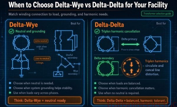
The connection choice is not a harmonic decision, it is a system decision that happens to have harmonic consequences. Here is what each one costs.
| Connection | Triplens from the load | Neutral heating | Escapes to primary | Typical use |
|---|---|---|---|---|
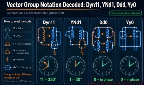
| Delta-wye (Dyn) | Circulate in delta | Full 3x on wye neutral | None, for balanced load | 480 to 208Y/120 distribution, the default |
| Delta-delta (Dd) | Circulate in both | None, no neutral | None | No 120 V loads, high reliability, arc furnace supply |
| Wye-wye, both grounded (YNyn) | Pass straight through | Full 3x, plus magnetizing third | All of it | Avoid unless a delta tertiary is added |
| Wye-wye with delta tertiary (YNyn+d) | Circulate in tertiary | Full 3x | None | Large units where a wye primary is needed |
Two things about that table are worth pulling out.
The delta-delta row is underrated. If you have no line-to-neutral load, Dd traps triplens on both sides, has no neutral to overheat, and keeps a phase pair in service if one winding fails. It is the best harmonic connection in the list and it is disqualified from most buildings by the absence of a neutral, not by anything electrical.
The wye-wye with tertiary row is where money disappears. The tertiary is usually rated at one third of the main kVA, which on a 1,000 kVA unit is 333 kVA and 231.5 amps of winding current. The circulating current at 40 percent third harmonic is 277.8 amps, which is 120 percent of what the tertiary is rated to carry. At 20 percent it is at 60 percent, at 30 percent it is at 90 percent, and at 33.3 percent it is exactly full. A one-third tertiary is adequate up to one third triplen content and not one amp beyond, and nobody puts that on the drawing.
The same connection is doing three jobs
A delta is not fitted for harmonics. It is fitted for three reasons, and the harmonic behaviour falls out of the first one. All three come from a single property, which is that zero-sequence current can circulate inside a delta but cannot cross it, and the consequences are worth separating because you only pay attention to one of them.
The first job is voltage. A delta gives the magnetizing third harmonic a path so the flux stays sinusoidal. Covered above.
The second job is insulation and cost. A delta winding has to withstand full line-to-line voltage across each phase, which makes it cheap at low voltage and expensive at high voltage. A wye winding only sees 58 percent of line voltage, which is why the high side of a 400 kV transformer is always wye. You put the delta where the current is high and the wye where the voltage is high, and on a 480 to 208Y/120 unit that means delta on the 480 side. Not because of harmonics. Because of copper and insulation.
The third job is zero sequence, and that is the one that affects your protection. Because the delta blocks zero sequence, a ground fault on the 208 volt side of a delta-wye cannot be seen by a current transformer in the 480 volt feeder. There is no zero-sequence path through the transformer, so there is no residual current on the primary to measure. Every ground fault protection device for that secondary has to be on the secondary, either a residual connection on the neutral or a ground sensor on the bonding jumper.
That is the same property the whole article is about, viewed from a different angle. The delta circulates the triplen and blocks the ground fault current for exactly the same reason: both are zero sequence, and the loop takes one and not the other.
And the magnitude matters. A solidly grounded delta-wye has a low zero-sequence impedance, close to its positive-sequence value, so a bolted line-to-ground fault on the 208 volt side draws a current comparable to the three-phase fault. On this 1,000 kVA unit that is around 48,000 amps either way. Ground fault current on a delta-wye service is not a small number that you can leave to a 30 milliamp device. This is the reasoning behind the ground fault protection requirement for solidly grounded wye services above 1,000 amps in 230.95, and it is the same reasoning that makes the neutral bonding jumper a piece of equipment rather than a wire.
Two units in series
Most buildings have at least two delta-wye transformers between the utility and the load, and the interaction surprises people.
Each delta-wye is an independent zero-sequence island. It traps whatever triplens its own secondary produces and passes nothing up. So the second unit in a cascade cleans its own floor, the first unit upstream sees no triplen from that floor, and neither one is helping the other. Each one pays its own heat bill.
| Arrangement | Where the triplens are trapped | Who pays |
|---|---|---|
| Utility, then Dyn, then load | In the Dyn delta | That unit, full circulating current |
| Utility, then Yyn, then Dyn, then load | In the lower Dyn delta | The lower unit only, the Yyn sees nothing |
| Utility, then Dyn, then Yyn, then load | Nowhere, the Yyn passes them | The utility sees all of it |
The third row is the one that bites. A wye-wye unit substation downstream of a delta-wye service looks fine on paper because the upstream unit is delta-wye, but the triplens from the load never reach that upstream delta. The Yyn passes them straight into its own primary and onto the 480 volt bus, and the delta-wye upstream of it is not in the path. That is how a building ends up with a harmonic problem at the point of common coupling despite having specified delta-wye everywhere.
The rule of thumb: the delta has to be the winding nearest the load. If it is not, it is not doing the job you bought it for. On a 500 kVA unit substation at 70 percent third harmonic, the secondary carries 971.5 amps per phase and 243.1 amps circulating on the 480 side, which is 70 percent of that winding’s rating. That heat exists whether or not anything upstream is trapping it.
The measurement that lies
You cannot verify the delta is working from the upstream side, and this trips up commissioning engineers who are doing everything right.
The whole point of the delta is that the triplen does not appear in the primary line currents. So a power quality meter on the 480 volt feeder will report a low THD and a clean waveform while the transformer circulates 278 amps and runs at 108 percent of winding rating. The measurement confirms the design intent and conceals the damage at the same time. Both statements are true.
What to measure instead:
- Secondary line currents, phase by phase. This is where the triplen lives before the neutral sums it. A three-channel meter on the 208 volt feeder gives you the spectrum you actually need.
- Neutral current, with a meter that reads true RMS and has bandwidth to at least the fifteenth harmonic. Many clamp meters roll off above 400 Hz and will under-report badly. A neutral at 3,331 amps of 180 Hz current can read as a fraction of that on the wrong instrument.
- Winding or top oil temperature, under known load. This is the only direct evidence of the circulating current, because it is the only thing that sees the heat. Compare against the temperature at the same kVA on a clean load.
- Phase-to-neutral voltage on the secondary. If the third harmonic voltage is significant here rather than on the primary, the delta is doing its job. If it shows up on the primary side, something upstream is wrong.
And on the primary side of a wye-wye, the diagnostic tool is a broken-delta connection on a set of voltage transformers. With the three secondaries in series and one corner left open, the voltage across the open corner is three times the zero-sequence voltage, which is the third harmonic content you are looking for. Line-to-line metering cannot see it. That is the same blindness described earlier, and it is why wye-wye problems get missed for years.
One worked example: 800 kVA of IT load
Put numbers on all of it. A data hall needs 800 kVA at 480 to 208Y/120, with a measured spectrum of 70 percent third, 40 percent fifth, 20 percent seventh, 10 percent ninth, 7 percent eleventh and 5 percent thirteenth.
Step 1, the spectrum. THD is 84.1 percent. K factor is 7.73, so the next standard rating is K-9. That is from the arithmetic, not from a rule of thumb.
Step 2, the currents. 800 kVA at 208 volts is 2,220.6 amps of total RMS. The fundamental is 2,220.6 divided by 1.306, which is 1,700 amps. Third harmonic is 70 percent of that, 1,190 amps per phase. Fifth is 680 amps. Seventh is 340.
Step 3, the neutral. Three times 1,190 is 3,570 amps. The phase conductors are rated 2,775.7 amps, so the neutral is at 128.6 percent of the phase rating. A standard neutral is 28.6 percent short. A 200 percent neutral is comfortable at 64 percent.
Step 4, the delta. Circulating current is 1,190 divided by 3.997, which is 297.6 amps, or 42.9 percent of the 694.4 amp winding rating. Combined with the 425 amps of fundamental in that winding, it puts the delta at 519 amps, which is 74.7 percent of its rating. Meanwhile the 480 volt feeder carries the fundamental only, 736.4 amps, which is 61.2 percent of nameplate. So the ammeter reads 61 percent, the winding runs at 75 percent, and the loss sits at 120 percent. That spread is the whole problem in one line.
Step 5, the heat. Load loss at this spectrum is 1.2017 per unit, on 9,000 watts of rated load loss. That is 10,815 watts instead of 9,000, an extra 1,815 watts, or 15,900 kWh a year, about 1,590 dollars.
Step 6, the capacity check. A standard 1,000 kVA unit at K of 7.73 keeps 73.0 percent of nameplate, which is 730 kVA. The load is 800. So the standard unit is 70 kVA short and the honest options are 1,500 kVA of standard iron or a K-9 at 1,000 kVA.
Step 7, the primary. Third, ninth and fifteenth harmonics do not appear on the 480 volt side. Fifth, seventh, eleventh and thirteenth do. Primary THD is 45.5 percent, not the 84.1 percent at the load. That is a genuine 46 percent reduction and it will still fail an IEEE 519 limit at most points of common coupling.
Step 8, what is left. If the 45.5 percent is a problem for the utility, the delta is not going to fix it, because what remains is not triplen. The options are a 12-pulse arrangement on the drive load if there is one, an active filter, or accepting the limit with the utility’s agreement. None of those are transformer decisions, which is the point of making the distinction.
Six things that go wrong
These are the ones I see, roughly in order of what they cost.
- “Delta-wye filters harmonics.” It does not filter, and it does not touch the fifth or the seventh. A spec written on this sentence will produce a building that passes on the transformer and fails at the point of common coupling, and the person who wrote it will spend a week looking at the transformer.
- Specifying by THD. Two loads at 50 percent THD need K-4 and K-9. Write the spectrum into the RFQ or accept whatever the vendor assumes, which will be the assumption that makes their unit cheapest.
- A 200 percent neutral on an 80 percent third harmonic load. The neutral wants 240 percent. Two hundred percent is a real improvement over one hundred and it is not enough, and the failure looks like a loose lug for the first two years.
- Commissioning from the primary. The 480 volt feeder reads 61 to 100 percent of nameplate on every job described in this article. It proves nothing. Measure the secondary spectrum or measure temperature.
- A one-third tertiary on a load above one-third triplen. The tertiary is at 120 percent at 40 percent third harmonic and there is no alarm for it. Tertiary heating shows up as gassing and eventually as a fault, and by then the unit is scrap.
- Assuming balance. The delta traps a balanced triplen and passes an unbalanced one. A panel schedule that was balanced at design and is not balanced after three tenant fit-outs has quietly lost the protection the connection was specified to provide.
What to put on the RFQ
The reason all of this matters commercially is that six lines on a requisition determine whether you get a transformer that lasts or one that gets replaced under warranty and fails again. Ask for these.
- The harmonic spectrum, per phase, to the fifteenth. Not the THD. The spectrum. The third harmonic separately, because it is the only one that sets the neutral.
- The neutral current in amps, computed as three times the third harmonic. Let the vendor size the neutral to that number rather than to a percentage.
- The K factor, or the load mix if you do not have a spectrum. A K-9 is not a premium in a data hall and it is an expensive mistake on a drive-fed machine.
- Guaranteed losses at the stated spectrum, not just at 60 Hz. A loss guarantee at a pure sine wave is worthless for a load with 84 percent distortion. Ask what the load loss is at your spectrum.
- The connection and the reason. Dyn where you need a neutral, Dd where you do not, and YNyn only with a tertiary whose rating you have checked against the triplen current.
- The tertiary rating if there is one, stated in amps of circulating current. One third of kVA is a starting point, not a specification.
Two things not to ask for. Do not ask for a “harmonic filter transformer” unless you mean a harmonic mitigating unit with a zigzag winding, which does something different and costs differently. And do not accept a price comparison between a standard unit and a K-rated unit without also comparing them at equal useful kVA, because at 73 percent derating they are not the same size.
The decision, in one table
Everything above reduces to five columns. If you have a spectrum, read across.
| Load | Connection | K factor | Neutral | What else |
|---|---|---|---|---|
| Office or data hall, switch-mode supplies at 70 to 80 percent third | Dyn | K-9 | 3 times the third harmonic, typically 210 to 240% | Detuning reactors on any capacitor bank |
| LED drivers at 40 percent third | Dyn | K-4 | 120% | Nothing, this one is easy |
| Six-pulse drives, no line-to-neutral load | Dd | K-9 | None | 12-pulse or a filter if the 5th and 7th matter |
| Six-pulse drives with DC link chokes | Dd or Dyn | K-4 | 100% | Often nothing, the choke did the work |
| Motors and resistance heat only | Dyn or Dd | K-1 | 100% | Nothing |
| Welders or an arc furnace | Dd | K-13 | None | Load balance and filtering, the delta will not hold an unbalanced triplen |
| Existing wye-wye you cannot replace | YNyn plus tertiary | By spectrum | 3 times the third harmonic | Tertiary rated in amps of circulating current, not a third of kVA |
Two entries in that table are worth defending. The Dd row is correct and almost never specified, because most buildings need 120 volts somewhere, and once you need 120 volts you need a neutral and Dd is off the table. If your drives are on a separate 480 volt bus with no 120 volt load, Dd is the better answer and it is cheaper than a K-rated Dyn because there is no neutral to oversize. The last row is the honest answer for a building that already has wye-wye units: you can retrofit a tertiary only at the factory, so in practice it means replacing the unit or accepting that the triplens are going to the utility and negotiating the limit.
FAQ
How does a delta winding trap triplen harmonics?
The three phase currents of a third harmonic are in phase with each other, so they form a zero-sequence set. In a delta they can circulate around the closed loop, and because each line current is the difference between two winding currents, the common component subtracts out. The harmonic never appears on the lines. Nothing is absorbed or filtered. The current keeps circulating in the copper and becomes heat.
Why is trapping triplen harmonics a good thing?
Two reasons. It keeps the magnetizing current’s third harmonic from flattening the flux, which would put a third harmonic voltage on every winding and raise the phase-to-neutral peak by that percentage. And it keeps load-generated triplens off the utility lines, which is what IEEE 519 is asking for. A building with heavy single-phase electronics presents a clean current to the grid because of this connection.
Does a delta-wye transformer remove the fifth and seventh harmonics?
No. The fifth is negative sequence and the seventh is positive sequence, so neither is common mode and neither cancels in a delta. They pass through transformed by the turns ratio. A six-pulse drive spectrum of 34.8 percent THD is still 34.8 percent on the primary. Only phase displacement, as in a 12-pulse arrangement, takes the fifth and seventh out.
How much current circulates in the delta winding?
In per unit, the circulating current equals the triplen current as a fraction of the fundamental. A 40 percent third harmonic load on a 1,000 kVA 480 to 208Y/120 unit puts 277.8 amps around the loop, which is 40 percent of the 694.4 amp winding rating but only 23 percent of the 1,202.8 amp line rating. The same current reads twice as large on the winding because the winding rating is the line rating divided by 1.732.
Why does the primary ammeter look normal when the transformer is overheating?
Because the triplen does not cross the transformer. The primary line current contains only the fundamental, so it reads exactly the load’s fundamental current, which at nameplate fundamental load is exactly the nameplate rating. The extra loss from the circulating current is real but invisible at the terminals. Only the secondary spectrum or the temperature shows it.
Is the neutral current 173 percent or 200 percent of the phase current?
Both numbers come from one curve. Neutral to phase RMS ratio is three times the third harmonic divided by the square root of one plus its square. That equals 1.732 at 70.7 percent third harmonic and 2.121 at 100 percent. The 200 percent figure is also the convention for K-rated neutral lug sizing. Neither is a fixed limit, so size the neutral at three times the measured third harmonic instead.
What K factor do I need?
Compute it from the spectrum rather than the THD. K is the sum of each harmonic current times its order, squared, divided by the sum of the currents squared. An office load at 84.1 percent THD comes out at K of 7.73, so K-9. A six-pulse drive at 34.8 percent comes out at 4.95, also K-9. Two loads at 50 percent THD can need K-4 and K-9 depending on which harmonic they contain.
Does a K-rated transformer trap harmonics?
No. It tolerates them. K rating describes how much extra eddy current loss the unit can survive before its winding temperature exceeds its insulation class. The harmonic current still leaves the secondary and still reaches the primary. A K-13 wye-wye unit will run cool and export every harmonic on the load side, so K rating and harmonic containment are separate decisions that are often sold as one.
What happens if a wye-wye has no delta winding?
The magnetizing third harmonic has no path, so the flux flattens and a third harmonic voltage appears in all three windings. Phase-to-neutral voltage distorts while line-to-line stays clean, because the subtraction cancels it. On a three-legged core that zero-sequence flux is forced through the tank, heating it and making noise, so the unit acts like a lossy delta tertiary. A five-legged or shell form core does not do that.
Can I use delta-delta instead?
Yes, if you have no line-to-neutral load. Dd traps triplens on both sides, has no neutral to overheat, and keeps two phases in service if one winding fails. It is the best harmonic connection available and it is ruled out of most commercial buildings only by the absence of a neutral, which is a load requirement rather than an electrical one.
How big should a delta tertiary be?
One third of the main kVA is the common convention, and it is adequate only up to one third triplen content. On a 1,000 kVA unit a one-third tertiary is 231.5 amps of winding current, and 40 percent third harmonic pushes 277.8 amps through it, which is 120 percent. State the tertiary rating in amps of circulating current rather than as a fraction of kVA.
Does load unbalance stop the delta from working?
Yes. A balanced triplen is purely zero sequence and cancels. An unbalanced set picks up positive and negative sequence components, which pass through a delta like any other harmonic. An arc furnace fed from delta-delta still puts large third harmonic current on the lines for exactly this reason. Load balance is part of the design, not a construction detail, if you are relying on the connection to keep the primary clean.