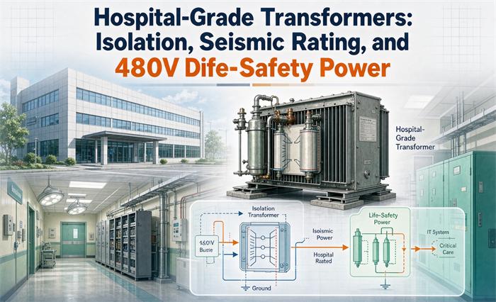
Three different codes hide under the phrase hospital-grade, and they buy three different things: an ungrounded 120V isolation panel for every operating room, anchorage that survives a design earthquake, and a life-safety feeder that never sees ground-fault protection. Most quotes cover the first and price the other two as line items nobody checked.
What “hospital-grade” actually means
The label gets used loosely. A buyer sees “medical-grade isolation transformer” on a product page and assumes it covers the whole building. It covers one room. Three separate requirements sit under the phrase, and they almost never share a piece of hardware.
| Discipline | Protects against | Governing text | Actual hardware | Who signs it off |
|---|---|---|---|---|
| Isolation | Microshock during a first ground fault | NEC 517.20 and 517.160, NFPA 99 | 5 to 37.5 kVA single-phase unit, 120V secondary, line isolation monitor | Electrical engineer, then the AHJ inspector |
| Seismic | Losing the unit off its anchor during shaking | ASCE 7 Chapter 13 via the adopted IBC | Qualified enclosure plus a stamped anchorage package | Structural engineer of record |
| Life-safety | Losing power to the branch that must survive an outage | NEC 517.29 through 517.35 | Distribution transformer on the emergency side of a transfer switch | Electrical engineer, then the commissioning agent |
Read the hardware column again. Isolation is a small unit per room. Seismic is a property of a box and four anchors. Life-safety is a routing decision on the one-line diagram. They are three separate lines on the same purchase order, and a supplier who quotes one number for “hospital grade” is quoting the first line only.
Isolation: 517.20 is the trigger, 517.160 is the design
Start with the occupancy, not the transformer. NEC 517.20(A) says a wet procedure location needs special protection against electric shock, and it gives you exactly two legal ways to provide it:
- A system that limits the first ground-fault current to a low value without interrupting power.
- A system that interrupts the supply when the ground-fault current exceeds the trip value of a Class A GFCI.
NFPA 99 is blunt about which rooms qualify. Under 6.3.2.3.4, an operating room is a wet procedure location unless the facility’s governing body runs a documented risk assessment and decides otherwise. That exception gets used, and it is the single most common reason a hospital ends up with fewer isolation panels than the drawings suggested.
When the room is classified wet, almost every US hospital picks option one. The reason is interruption. A Class A GFCI trips at roughly 5 mA of leakage, which ends the case, kills the anesthesia machine mid-procedure, and drops the field lights. An isolated power system absorbs that same fault, alarms, and keeps the case running. You are not buying cleaner power. You are buying the right to finish the operation.
NEC 517.20(B) then hands the design over to 517.160: where an isolated power system is used, the equipment has to be listed as isolated power equipment, and the system has to be built to 517.160.
Why the secondary is ungrounded
The isolation transformer feeding the panel has no neutral on the secondary. Neither circuit conductor is referenced to ground. Touch one conductor while standing on a wet floor and there is no return path, so no current flows and no breaker trips. That is the whole trick.
A second fault, on the other conductor, is what creates a hazard, and that is exactly what the monitor watches for. Everywhere else in the hospital, grounding is the safety mechanism. Inside the isolated system, the absence of a ground reference is the safety mechanism, which is why the system must be supervised and why the monitor cannot be treated as an optional accessory.
The 5 mA alarm, and the 40 µA the hardware already spent
NEC 517.160(B)(1) sets the line isolation monitor threshold at 5.0 mA of total hazard current at nominal line voltage. The monitor calculates resistive and capacitive leakage combined, and it must sound an audible alarm and light a red lamp when that total reaches 5 mA.
Here is what the vendor pages leave out. UL 1047 caps the leakage the hardware itself contributes: 20 µA for the transformer and 40 µA for the panel, both measured at 5 kVA and 120V. Forty microamps is 0.8 percent of the 5,000 µA alarm budget. The other 99.2 percent is spent by the cords, the receptacles, and the capacitance of the branch wiring you install.
That ratio is why the wiring rules inside an isolated system are so tight. Long branch circuits, extra receptacles per circuit, and reduced-capacitance insulation choices are not style preferences. Each one eats into a budget that started at 5 mA and will never grow. A panel that passes commissioning on day one can drift into nuisance alarms after a renovation adds three more outlets and 60 feet of conduit.
What UL 1047 tests that a general-purpose transformer is not tested for
UL 1047 is the standard for isolated power systems equipment, and its seventh edition was published March 26, 2025. The scope is equipment rated 600V or less, installed in nonhazardous areas of health care facilities per NEC Article 517 and NFPA 99. Three construction details separate it from a UL 506 general-purpose transformer:
- The primary and secondary windings must have no electrical connection, enforced either by a copper barrier at least 0.005 inch thick between coaxial windings, or a physical spacing of at least 1/2 inch, or an insulating barrier of the phenolic type at 0.028 inch or more.
- The line isolation monitor is part of the listed assembly, and it has to meet UL 1022.
- Primary leads must be 20 AWG or larger and protected by a fuse or breaker rated no higher than 15 A.
A general-purpose isolation transformer will not carry these. If the submittal does not name UL 1047 for the panel, you are looking at a transformer, not an isolated power system, and 517.160 does not accept the substitution. In Canada the paired mark is CSA Z32.2.
One more construction note worth knowing before you approve a shop drawing: UL 1047 requires the core to be grounded or fully insulated, and the transformer lead insulation to be V-0 flame rated. These are the details that show up as a rejected submittal, not as a field failure.
Sizing the operating room unit
The isolated system serves only the room’s isolated receptacles, not the room’s whole electrical load. That keeps the unit small. North American catalogue sizes run 3, 5, 7.5, 10, 15, 25, and 37.5 kVA, single-phase, with a 120V secondary. Primary is whatever the house system offers, usually 480V or 277V.
| kVA | Secondary amps at 120V | Primary amps at 480V | Primary amps at 277V |
|---|---|---|---|
| 3 | 25.0 | 6.3 | 10.8 |
| 5 | 41.7 | 10.4 | 18.1 |
| 7.5 | 62.5 | 15.6 | 27.1 |
| 10 | 83.3 | 20.8 | 36.1 |
| 15 | 125.0 | 31.3 | 54.2 |
| 25 | 208.3 | 52.1 | 90.3 |
| 37.5 | 312.5 | 78.1 | 135.4 |
A 10 kVA unit is the common answer for a general operating room. At 120V that is 83.3 A of secondary capacity, which covers the table, the lights, the anesthesia machine, the electrosurgical unit, and the documentation cart with room to spare. Ten rooms at 10 kVA each is 100 kVA of connected isolation capacity, but the primary draw spreads across phases at 20.8 A per room, so the upstream feeder impact is far smaller than the kVA total suggests.
Two sizing habits that save change orders. First, ask whether the room’s imaging or laser equipment is on the isolated panel or on a separate circuit, because a 37.5 kVA upright unit and a 10 kVA low-profile unit are different footprints, different weights, and different wall openings. Second, put the monitor’s remote annunciator location on the drawing. A red lamp inside a locked electrical closet satisfies nobody.
Seismic rating: the pillar almost nobody writes about
Search the exact phrase and the top results talk about isolation or K-rating. Almost none of them tell you how a transformer is qualified to stay bolted down through an earthquake. Yet a hospital is Risk Category IV, the highest occupancy class, and the transformers feeding its life-safety branch are supposed to be energized after the shaking stops.
Risk Category IV and Ip = 1.5
Seismic demand in the US comes from ASCE 7, pulled in through whichever edition of the International Building Code your jurisdiction adopted. Hospitals land in Risk Category IV under ASCE 7 Table 1.5-1, mirrored in IBC Table 1604.5. For nonstructural components, the number that matters is the component importance factor, Ip, and it is 1.5 wherever the component has to function after an earthquake to protect life. A hospital transformer qualifies.
Ip of 1.5 is not a gentle bump. It sits in the denominator of the response modification term, so it multiplies the design force by 1.5 relative to the same unit in an office building at the same site.
The force equation, worked on a 750 kVA unit
ASCE 7-16 Equation 13.3-1, which still governs most projects on the 2021 IBC, reads:
Fp = 0.4 × ap × SDS × Wp ÷ (Rp ÷ Ip) × (1 + 2z/h)
Use a 750 kVA cast-resin dry-type with enclosure at 8,000 lb, bolted to a housekeeping pad at mid-height of a four-story building, on a site with SDS of 1.0 g. For mechanical and electrical equipment, ap is 1.0 when the unit is rigid and 2.5 when it sits on vibration isolators, and Rp is 2.5 either way.
| Mounting and elevation | Fp | As a share of weight |
|---|---|---|
| Rigid, at grade (z/h = 0) | 3,600 lb, minimum governs | 0.45 g |
| Rigid, mid-height (z/h = 0.5) | 3,840 lb | 0.48 g |
| Rigid, at roof (z/h = 1.0) | 5,760 lb | 0.72 g |
| On springs, mid-height | 9,600 lb | 1.20 g |
| On springs, at roof | 14,400 lb | 1.80 g |
Two results deserve a second look. At grade the equation output (1,920 lb) falls under the floor of 0.3 × SDS × Ip × Wp, so the minimum controls. And the spring-mounted row is not a typo: ap of 2.5 doubles the demand, which means a vibration isolation detail added for acoustics quietly doubles the seismic load on the same four anchors.
Anchors are designed with overstrength
The force above is not what the anchor sees. Where a component is anchored into concrete or masonry, ASCE 7 requires the anchorage to be designed using the overstrength factor from Table 13.6-1, which is 2.5 for most mechanical and electrical equipment. Apply it to the mid-height rigid case and the anchor design shear becomes 9,600 lb on an 8,000 lb unit.
Then read the exception that catches people. If the unit sits on vibration isolators with a clearance greater than 1/4 inch, the design force on the restraint doubles. Take the rooftop row, double it for the isolator clearance, and apply the overstrength factor: 14,400 lb becomes 28,800 lb, and the anchor calculation lands at 72,000 lb of shear on a unit that weighs 8,000 lb. That is the arithmetic behind the phrase “seismically qualified anchorage,” and it is why a bolt kit picked from a shelf is not the answer.
ASCE 7-22 rewrote the equation, and rooftops feel it
The 2024 IBC adopts ASCE 7-22, and Chapter 13 was rewritten more thoroughly than in any edition since the equation appeared. The old form collapsed three ideas into two switches. The new form splits the building’s amplification from the component’s response:
Fp = 0.4 × SDS × Ip × Wp × [Hf ÷ Rμ] × [CAR ÷ Rpo]
The bounds are unchanged at 0.3 and 1.6 times SDS × Ip × Wp. Hf replaces (1 + 2z/h) and adds a tenth-power term, Hf = 1 + a1(z/h) + a2(z/h)^10, with a1 = 1/Ta capped at 2.5 and a2 = 1 − (0.4/Ta)². For a building with Ta of 0.5 second, Hf at mid-height works out to 2.00, which matches the old linear term exactly. At the roof, Hf is 3.36 against the old 3.0, roughly 12 percent more. The tenth-power term is negligible everywhere except near the roof, and that is precisely where it is meant to bite.
Rμ is new. It credits the ductility of the supporting structure, Rμ = [1.1R ÷ (Ie × Ω0)]^0.5, never less than 1.3 above grade. A ductile frame delivers less acceleration to the equipment sitting on it, and the 7-22 equation finally says so. If your project is on the 2024 IBC, ask the structural engineer which edition the nonstructural calculations used before you accept a seismic package written to the older form.
HCAI, which most people still call OSHPD
If the project is in California, a second regulator joins the conversation. On July 1, 2021, the Office of Statewide Health Planning and Development was reorganized into the Department of Health Care Access and Information, and OSHPD continues as the office inside HCAI that regulates hospital design and construction. The program names kept the old prefix, which is why the industry still says OSHPD seismic certification.
Three preapproval paths matter, and they are not interchangeable:
- OSP, the Special Seismic Certification Preapproval, for active or energized equipment. Substantiation is by shake-table testing to ICC-ES AC156. This is the one that applies to a transformer that has to keep working.
- OPM, the Preapproval of Manufacturer’s Certification, for the seismic design of supports and attachments. It is not a product certification, and it does not substitute for an OSP.
- PCS, for prefabricated components and systems. Not a route for a transformer.
An OSP listing is model and configuration specific, and it only helps if the certified limits cover your project’s demand. Pull the listing number and check it against your unit before the submittal goes out. Also worth knowing: static cyclic testing to ANSI/ASHRAE 171 does not replace the AC156 shake-table requirement for energized hospital equipment, whatever a data sheet implies.
Outside California, none of this is mandated. Ask for the same evidence anyway. A manufacturer who can produce shake-table data and a calculated anchorage to your Seismic Design Category is handing you something a reviewer can check. One that ships a standard pad and says bolt it anywhere is handing you a schedule risk.
Four lines for the RFQ
- Seismic qualification to the adopted IBC and ASCE 7 edition, Risk Category IV, Ip = 1.5.
- HCAI OSP preapproval number where the jurisdiction requires it, with the certified model and configuration stated.
- Stamped anchorage drawing showing bolt pattern, embedment, edge distance, and allowable load, coordinated with the structural engineer’s slab.
- Shake-table or analysis report the manufacturer will release to the engineer of record.
Add a fifth question that separates real suppliers from catalog resellers: is the enclosure part of the qualification, or only the coil? A dry-type core and coil in a sheet-metal box is only as qualified as the box and its brackets, and the brackets are usually the first thing to fail.
Our low-noise cast-resin installation for a city hospital is an example of a package where the submittal evidence carried as much weight as the electrical rating.
Life-safety power: the Type 1 essential electrical system
Life-safety power is shorthand for the Essential Electrical System in NEC Part III of Article 517. Hospitals run a Type 1 system, which 517.29 requires for Category 1 spaces, the classification the 2023 NEC adopted in place of the older critical care wording. The confusion comes from treating emergency power as one bucket. It is three branches, and they have different rules for transfer time, ground-fault protection, and even which conduit they can share.
| Branch | What sits on it | Restore time | GFP allowed | Shared raceway |
|---|---|---|---|---|
| Life Safety, 517.33 | Egress lighting, exit signs, fire alarm, nurse call infrastructure, communications | 10 seconds | No | No, must be independent |
| Critical, 517.34 | OR and ICU receptacles, task lighting, blood bank refrigeration, essential imaging | 10 seconds | No | No, must be independent |
| Equipment, 517.35 | Chillers, air handlers, boilers, elevators, central plant | Delayed transfer permitted | Permitted | May share with normal wiring |
Ten seconds, and the 150 kVA shortcut
NEC 517.32 requires the life safety and critical branches to be connected to the alternate source so that all required functions are restored within 10 seconds of a normal outage. The equipment branch can arrive later, on a timed delay or even manually, because a chiller restart does not kill anybody in the first minute.
There is one allowance that changes the gear count. Under 517.31(B), a single transfer switch and its downstream distribution may serve one or more branches where the maximum demand on the essential electrical system is 150 kVA or less. Above that, each branch gets its own transfer switch. On a small clinic that allowance saves real money. On a hospital it is irrelevant, and the three-transfer-switch arrangement is what you should expect to see priced.
Why ground-fault protection is banned on two of the three branches
This is the clause that surprises suppliers. Where ground-fault protection of equipment is installed on the service disconnect per 230.95, 517.17 requires a second level of GFP on the next downstream feeder, with the two levels selectively coordinated and at least 6 cycles of separation. Pickup is capped at 1,200 A, and for fault currents of 3,000 A or more the maximum delay is 1 second.
Then 517.17(B) removes the tool entirely from the place you would most want it: automatic ground-fault protection is not permitted on the load side of the essential system transfer switches. No GFP on the life-safety branch. No GFP on the critical branch.
The logic is not subtle. A nuisance GFP trip on the life-safety branch takes out exit signs and fire alarm notification during the exact emergency that branch exists to survive. So those two branches run without GFP, coordination is done with overcurrent devices and selective settings, and the fault is cleared by the device closest to it. If a supplier proposes a GFP relay on a critical-branch feeder as an upgrade, that is a code violation with a nice brochure.
Note the distinction that trips up plan reviewers: the life-safety branch still needs ground-fault indication at the generator, and it is subject to Article 700 requirements including a listed surge protective device on its panelboards. Indication is not protection. One alarms, the other disconnects.
Wiring separation is where the budget goes
NEC 517.30(C)(1) requires the life safety and critical branches to be kept entirely independent of all other wiring and equipment. They cannot enter the same raceways, boxes, or cabinets as each other or as any other wiring. The equipment branch is exempt and may share pathways with normal power.
On a new building this is a drawing discipline. On a renovation it is a cost event: two additional conduit runs from the switchgear to the far end of a floor, two additional pull boxes, and a ceiling plenum that suddenly has no room. Put the separation requirement on the electrical contractor’s scope note, not just on the one-line.
Sizing the critical branch step-down
The critical branch is the workhorse. It carries the red receptacles in operating rooms, PACUs, cath labs, and every high-acuity space, and most of that load is 120V, which means step-down transformers. Two numbers rule the design:
- Keep the individual critical-branch step-down units under 112.5 kVA. A 112.5 kVA unit at 480V draws 135 A on the primary, and step-down transformer inrush runs 6 to 8 times that, so 1,080 A of momentary current. The breaker’s instantaneous pickup has to sit above that and still coordinate with the feeder ahead of it. Shrinking the sub-unit is cheaper than buying an adjustable-trip breaker for a 200 A panelboard.
- Expect the life-safety branch itself to be small. It rarely needs more than 200 A at 480V, which is about 166 kVA, and at that size thermal-magnetic breakers leave very little room for coordination tolerance.
For the transformers feeding these branches, the practical requirement is placement on the emergency side of the transfer switch. A transformer on the normal side that feeds a red receptacle panel is a drawing error that passes inspection and fails the first outage.
Redundant grounding and the 14 receptacles
Two more numbers belong in the specification. NEC 517.13 requires two equipment grounding paths for branch circuits serving patient care spaces: the wiring method itself must qualify as an equipment grounding conductor under 250.118(A), and a separate insulated copper conductor must run inside it. Interlocked Type MC cable does not qualify, which is why hospital corridors are full of EMT.
NEC 517.19(B)(1) requires at least 14 hospital-grade receptacles at each Category 1 patient bed location, supplied by at least two branch circuits. The design target facilities hold is under 0.5 V between any two exposed conductive surfaces a patient could touch at once. That figure is a design intent rather than a single code line, so confirm it with the engineer of record.
If a submittal leans on IEC 60076 or IEC 61558 for a US hospital, stop there. Those are product standards, not the code basis, and our IEC 60076 versus ANSI/IEEE comparison explains why a US spec is built on NEC and NFPA instead. The one place IEC enters legitimately is the equipment inside the room, through IEC 60601-1.
Dry-type is the default indoors, and noise decides the rest
Hospitals almost never put an oil-immersed transformer inside an occupied building. The liquid hazard and the containment requirements conflict with NFPA 99 and the indoor fire provisions, and the review is not worth the argument. Dry-type construction removes the hazard: cast resin is self-extinguishing and produces no toxic smoke, which matters in a building that cannot be quickly evacuated.
Noise is the constraint that gets under-specified. A 7.5 kVA hospital isolation transformer is commonly rated at 35 dB(A) maximum, which is quieter than the room it sits in. A 750 kVA cast-resin distribution unit is not, and putting one above a patient room turns an electrical decision into a facilities complaint. Specify the sound level in dB(A) at a stated distance, and specify where the unit goes.
Our dry-type transformer explainer covers the cast-resin versus VPI choice, and the oil-immersed versus dry-type comparison lays out why hospitals default to dry. For the hardware itself, the dry-type product line and the special transformers range cover medical and seismic-configured builds.
K-rating: scope it to imaging, not the building
MRI, CT, and angiography suites draw current in pulses and push harmonic content back into the feeder. A K-rated transformer is built with a winding that tolerates the extra eddy-current heating that comes with it. K-13 means the design accommodates a harmonic spectrum producing 13 times the eddy loss of pure fundamental current, and it is the usual answer for an imaging feeder. K-20 exists for the worst cases.
The mistake is applying it everywhere. A K-13 transformer on a lighting panel that will never see harmonics is money spent on a problem that does not exist, and hospitals with a standard-everything procurement habit do exactly that. Scope the K-rating to imaging feeders and large VFD loads, keep the rest standard dry-type, and put the reasoning in the basis of design so it survives value engineering.
Hospital transformer RFQ checklist
Group the order the way the code groups the requirements. This is the version that survives a plan review.
| Group | State on the RFQ | Ties to |
|---|---|---|
| Isolation | UL 1047 listed isolated power system, 5 to 37.5 kVA, 120V secondary, LIM alarming at 5 mA | NEC 517.20, 517.160 |
| Seismic | IBC and ASCE 7 edition named, Risk Category IV, Ip = 1.5, HCAI OSP number if in California | ASCE 7 Ch. 13 |
| Anchorage | Stamped drawing, bolt pattern, embedment, overstrength factor applied, isolator clearance stated | ASCE 7 Table 13.6-1 |
| Life-safety | Unit on emergency side of the transfer switch, no GFP on life safety or critical feeders | NEC 517.17, 517.32 |
| Grounding | Two-path equipment grounding, insulated copper EGC in metal raceway, 0.5 V equipotential target | NEC 517.13 |
| Construction | Dry-type, cast resin or VPI, sound level in dB(A) at a stated distance, enclosure included in the seismic qualification | NFPA 99, project acoustics |
| Harmonics | K-13 for imaging and VFD feeders only, stated per feeder not per building | Transformer design |
| Efficiency | Meets 10 CFR 431.196, amended standards effective April 23, 2029 | DOE distribution transformer rule |
| Evidence | Routine test report, witness test option, seismic submittal package, OSP listing number | Factory test routine |
Five mistakes that fail inspection
- Citing the wrong UL standard. UL 1043 covers hospital signaling and nurse call equipment. Isolated power systems equipment is UL 1047. A submittal that names 1043 for an operating room panel gets rejected, and it signals that nobody read the standard.
- Specifying seismic for the small unit only. The OR isolation panel gets the attention because it is visible. The 750 kVA feeding the critical branch is the one whose anchorage failure takes down a whole floor, and its mounting is usually a generic pad nobody calculated.
- Putting GFP on a critical-branch feeder. NEC 517.17(B) prohibits automatic ground-fault protection on the load side of the essential system transfer switches. It arrives disguised as a safety upgrade.
- One K-rating for the whole hospital. Standardizing on K-13 inflates every package on the job and fixes nothing on the loads that do not produce harmonics.
- No acoustic number and no location. A dry-type unit that meets every electrical line and hums above a patient room is a field rejection with a change order attached. Put dB(A) and the room on the order.
FAQ
What makes a transformer hospital-grade? Three separate qualifications, not one. It has to support an isolated power system listed to UL 1047 where the room is a wet procedure location, it has to be seismically qualified and anchored for Risk Category IV with Ip of 1.5, and it has to sit on the emergency side of a transfer switch if it feeds the life-safety or critical branch. A product page that says hospital-grade usually means only the first.
Does every operating room need an isolated power system? Not automatically. NEC 517.20 requires special protection in a wet procedure location, and an isolated power system is one of two permitted methods, with Class A GFCI protection as the other. NFPA 99 treats operating rooms as wet unless the facility’s governing body documents a risk assessment that says otherwise. In practice hospitals choose isolation because a GFCI trip ends the procedure.
What is the difference between UL 1047 and UL 506? UL 1047 covers isolated power systems equipment for health care facilities under NEC Article 517 and NFPA 99. It requires winding separation by a copper barrier of at least 0.005 inch or a 1/2 inch gap, an integral line isolation monitor to UL 1022, and primary leads protected at 15 A or less. UL 506 is a general-purpose transformer standard and does not carry those requirements, so it cannot be substituted for an operating room panel.
How big is the isolation transformer for an operating room? Most US operating rooms use a single-phase unit between 5 and 15 kVA with a 120V secondary, and 10 kVA is the common answer. At 120V, 10 kVA gives 83.3 A of secondary capacity and draws 20.8 A on a 480V primary. Catalogue sizes run 3, 5, 7.5, 10, 15, 25, and 37.5 kVA. Confirm against the room’s isolated receptacle schedule rather than a rule of thumb.
Do hospital transformers need seismic certification? Every unit whose failure would take down a life-safety or critical branch should be seismically qualified and anchored, which in a hospital means most of them. California requires HCAI preapproval, with OSP special seismic certification for energized equipment proven by shake-table testing to ICC-ES AC156. Elsewhere, ask for the same analysis and a stamped anchorage drawing even when the jurisdiction does not mandate it.
Why is ground-fault protection not allowed on a life-safety feeder? NEC 517.17(B) prohibits automatic ground-fault protection on the load side of the essential system transfer switches, which covers the life-safety and critical branches. A nuisance trip would drop exit signs, fire alarm notification, and patient care receptacles during the emergency those branches exist to survive. Coordination is achieved with overcurrent devices and selective settings instead of GFP.
Should a hospital use a dry-type or oil-immersed transformer? Dry-type indoors, essentially without exception. Oil-immersed units bring a liquid hazard and containment requirements that conflict with NFPA 99 and the indoor fire provisions. Cast-resin dry-type is self-extinguishing and produces no toxic smoke, which matters in a building that cannot be evacuated quickly. Oil remains a reasonable option for a detached yard or pad-mounted service far from occupied space.