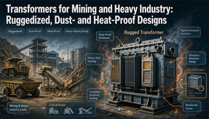
Ruggedized is not an option box. On a mine site it is four numbers that multiply: dust sealing, ambient above 40°C, altitude above 1,000 m, and drive harmonics. A 2,500 kVA unit in a sealed enclosure at 50°C and 2,000 m is a 1,460 kVA unit once the drives are counted. You size the chain, then pick the frame.
This page is the sizing chain. If you already know your kVA and just want the hardware family, the industrial metallurgy range and the industrial oil-immersed units cover the model lines. What follows is the part that decides whether the model line survives year three.
Why a Mine Transformer Is a Different Purchase
A plant buys a transformer and puts it in a room. A mine buys one and drags it across a pit every few weeks, then leaves it in a cloud of abrasive dust at 48°C with a crusher shaking the ground forty feet away.
That difference shows up in four places, and each one has a number attached:
| Threat | What actually fails | The number that matters |
|---|---|---|
| Dust | Insulation tracking, clogged cooling ducts, seized fans | IP first digit, creepage distance, filter interval in weeks |
| Heat | Insulation aging, not melting | 1% capacity per °C over 40, aging doubles every 6 to 8 K |
| Harmonics | Winding hot spots at the ends, neutral overload | K-factor, which for a 6-pulse drive lands near 5.4 |
| Vibration and handling | Loose core clamps, cracked bushings, shifted windings | Transport shock in g, continuous vibration as a spectrum |
Buy against those four and the rest follows. Buy against a catalog page and you get a unit that meets its nameplate in a lab and misses it on your bench.
One more thing before the numbers. The word rugged gets used to sell three different upgrades: a heavier tank, a better coating, and a genuinely derated core. Only the third one changes capacity. Ask which one you are being quoted.
The Regulatory Fork: NEC Stops at the Portal
This is the part almost no supplier explains, and it decides your enclosure before any electrical question comes up.
NEC 90.2(B)(2) excludes two categories outright: installations underground in mines, and self-propelled mobile surface mining machinery together with its trailing cable. Those are not NEC work. They are Mine Safety and Health Administration work, under Title 30 of the Code of Federal Regulations.
Everything else on the property stays inside the NEC. The office, the shop, the warehouse, the fixed processing plant, the substation yard feeding them. So a single mine site can have both regimes running at once, and the fence line between them is not where people assume it is.
What that means in practice:
| Location | Governing rules | What it changes about the transformer |
|---|---|---|
| Underground coal | 30 CFR Part 18 and Part 75, MSHA approval | Permissible enclosure, explosion containment, no free-breathing oil tank |
| Underground metal or nonmetal | 30 CFR Part 57 plus state mining rules | Fire-resistant enclosure, containment, often dry-type |
| Mobile surface equipment and its trailing cable | 30 CFR Part 77 | Skid or trailer mount, two-ground system, ground check monitoring |
| Fixed surface plant, offices, shops | NEC, including Article 450 and 250 | Standard UL listing, standard overcurrent protection, standard grounding |
If your unit is going underground in coal, an MSHA approval number is not paperwork you add at the end. The enclosure is tested as a pressure vessel, the cable entries are part number specific, and the surface temperature limits are part of the approval. A standard NEMA 3R tank with a nice coating does not become permissible because someone stamped it.
If your unit is going into the fixed plant on the surface, the reverse is true. MSHA approval buys you nothing, and the authority having jurisdiction wants UL listing and an NEC 450 compliance path.
Get this fork wrong and the failure is not subtle. It is a unit that cannot be energized, sitting on a concrete pad, sixteen weeks from a replacement.
The Voltage Ladder, and What It Does to Current
Mine distribution is not the same ladder as a commercial building, and the rungs are historical rather than mathematical.
| Stage | Typical voltage | Notes |
|---|---|---|
| Utility delivery | 46 kV, 34.5 kV, 24.9 kV, 13.8 kV | Varies by region and by how old the service is |
| Mine distribution | 13.8 kV, 7,200 V, 4,160 V | The 7,200 V level became standard once shovels outgrew 4,160 V |
| Large mobile equipment | 7,200 V, 13.8 kV, up to 23 kV | Above roughly 100 cubic yard capacity, 13.8 kV took over |
| Shovel and dragline auxiliary | 480Y/277 V | Service power, lighting, small motors |
| Camp and office | 120/240 V single-phase | 15 to 75 kVA is the usual range |
The history matters because you inherit it. Equipment built for 4,160 V is still in service, and 4,160 V was the standard for machinery at or below about 1,500 hp. New large machines came in at 7,200 V, then 13,800 V, then 23,000 V as connected horsepower climbed. A single pit can end up needing three voltage levels because it bought machines in three different decades.
Current follows the square root of three, and the numbers are worth memorizing because they set every cable and breaker downstream.
One ampere per kVA, three-phase, is 1,000 divided by the square root of three times the line voltage. At 7,200 V that is 0.0802 A per kVA. At 480 V it is 1.2028 A per kVA. At 34.5 kV it is 0.0167 A per kVA.
A 2,500 kVA power center with a 34.5 kV primary and a 7,200 V secondary:
- Primary full load current: 2,500 × 0.0167 = 41.8 A
- Secondary full load current: 2,500 × 0.0802 = 200.5 A
Those two numbers explain the whole physical layout. The primary side is a cable and a small switch. The secondary side is 200 A at 7,200 V, which is why mine power centers carry their own trailing cable couplers and why the cable is the expensive part of the move.
Drop the same 2,500 kVA to 480 V and you get 3,007 A. That number is a wall. Above 800 A, NEC 240.4(C) does not let you round up to the next breaker size, and the conductor you need is a bus, not a cable. This is why mine power centers stop at 7,200 V and let a smaller 480 V unit handle the auxiliaries.
Dust: What an IP Rating Does and Doesn’t Tell You
The IP code has two digits and only one of them is about dust. The first digit covers solids, the second covers water.
| Rating | First digit meaning | What it actually buys you on a mine |
|---|---|---|
| IP54 | 5, dust protected | Some dust gets in but not enough to interfere. Splash from any direction |
| IP55 | 5, dust protected | Same dust, plus low-pressure jets. The common outdoor mining spec |
| IP65 | 6, dust tight | No dust ingress at all. Water jets. This is where the heat problem starts |
| IP66 | 6, dust tight | No dust, powerful jets. Washdown rated |
| IP67 | 6, dust tight | Temporary immersion. Rarely relevant for a fixed transformer |
Two things the code does not tell you. It says nothing about corrosion, and nothing about ultraviolet degradation. A painted IP66 enclosure in a high-UV desert will still fail at the gasket and the coating long before the ingress number is challenged. For corrosion you need a separate specification, usually an ISO 12944 category, and for a mine with acid drainage or a coastal concentrator you are specifying C5.
The Sealed Box Problem
Here is the trade nobody puts on the same page. A transformer rejects heat by moving air. Seal the enclosure to keep dust out and you have removed the air.
A sealed enclosure runs 10 to 15 K hotter inside than the air outside it. On a 45°C day that is an internal ambient of 55 to 60°C, which is 15 to 20 K over the reference the nameplate was built on. At the planning rule of 1% per °C, that is 15 to 20% of capacity gone before you have accounted for anything else.
There are only three honest ways out:
- Buy the capacity back. Oversize the unit so that the derated output still covers the load. Costs money, works, and needs to be done in the sizing sheet rather than discovered later.
- Use forced cooling with filtration. Fans pull air through filters into the enclosure. This works and it converts your transformer into a maintenance item. In a mine the filter change interval is measured in weeks, not months, and the fan motor is now a failure point.
- Go to a higher insulation class and a hotter design. A Class H unit at 125 K rise has more thermal headroom than a Class F at 100 K. You are buying margin with insulation money instead of copper money.
What you cannot do is specify IP66 and Class F at 100 K rise and expect both to hold. Something gives, and it gives in the winding.
Conductive Dust Is a Different Problem
Abrasive dust wears things out. Conductive dust shorts them out. Coal dust and metallic ore dust are both conductive when they settle wet, and they settle on exactly the surfaces you need clean: bushing tops, cable termination boots, and the creepage path between phases.
This is a creepage problem, not an ingress problem. An IP65 enclosure with a cable gland that weeps will still track, because the dust arrives as airborne fines and leaves as a conductive film on the insulating surface. What you specify is a longer creepage distance and a hydrophobic shed profile, not a higher IP number.
For the enclosure itself, the two useful specifications are a stainless or marine-grade aluminum cabinet in a coastal or acid environment, and hot-dip galvanizing to ASTM A123 for the skid and frame. Coating thickness on a C5 site runs 80 micrometers minimum for the epoxy primer plus the polyurethane topcoat, and that is a number you can put in the purchase order and inspect.
Breathers, or the Lack of Them
An oil-immersed transformer breathes. It heats, the oil expands, air leaves. It cools, the oil contracts, air comes back in. On a dusty site, every one of those breaths pulls fines into the conservator through the silica gel.
Two designs solve it. A hermetically sealed tank with a diaphragm, where the oil expansion is absorbed inside a sealed volume and nothing crosses the boundary. Or a sealed tank with a positive-pressure nitrogen blanket.
Both rule out a Buchholz relay, because there is no gas space to collect in. Both are common in the sizes mines buy. If your specification says conservator with breather, you have specified a maintenance schedule along with a transformer.
Heat: Running the Derating Chain
This is where the money is. Four factors, applied in sequence, and the order matters only because you need to state your basis in the spec.
Ambient
The reference condition built into a nameplate is a maximum ambient of 40°C, a daily average of 30°C, and an annual average of 20°C. Above 40°C you derate.
The planning rule most manufacturers publish is 1% of rated kVA per °C above 40. A 50°C site loses 10%. A 55°C site loses 15%, and 55°C is a real number in the Pilbara, in northern Chile, and in a concentrator building anywhere.
A more generous figure exists, roughly 0.4% per °C, and it comes from older guidance for Class A insulation. It is not wrong, it is for a different insulation class at a different temperature rise. If a supplier quotes you 0.4% and you are buying Class F or H, ask which basis they used. Two quotes with the same kVA and different derating bases are not the same transformer.
Altitude
Thinner air removes less heat, and it also changes the dielectric picture. The planning rule is 1% per 100 m above 1,000 m. IEC 60076-7’s own thermal correction is closer to 0.4% per 100 m.
Those two numbers give very different answers at 4,000 m, which is a normal elevation for a Andean copper mine. At the conservative 1% rule, 4,000 m costs 30%. At the IEC 0.4% rule, it costs 12%.
Neither is a lie. What matters is that the number appears in the submittal with its source attached, so a reviewer can see whether it is a design basis or a guess. Write the basis into the specification and the argument never happens.
Altitude also needs a dielectric check that has nothing to do with thermal derating. Above 1,000 m, external insulation clearances are corrected for reduced air density. Ask for the altitude-corrected clearance table for your BIL, not the catalog clearance. A unit that passes its impulse test at sea level and arcs across a bushing at 4,000 m passed the wrong test.
The Enclosure
Covered above: a sealed cabinet adds 10 to 15 K to the ambient the transformer actually sees. If you are running the chain, add it to the ambient number before you apply the percentage, and do not add it twice.
Putting the Three Together
They multiply, they do not add. That is the point people miss.
| Condition | Factor | Basis |
|---|---|---|
| 50°C ambient | 0.90 | 1% per °C over 40 |
| 2,000 m altitude | 0.90 | 1% per 100 m over 1,000 |
| Sealed IP65 cabinet | 0.90 | 10 K internal rise, treated as ambient |
| Combined | 0.729 | 0.90 × 0.90 × 0.90 |
A 2,500 kVA unit under those three conditions is worth 1,822 kVA. Add drive harmonics and it drops further.
What That Costs in Insulation Life
Derating is not caution for its own sake. It buys back years.
Insulation ages by an Arrhenius relationship, and IEEE C57.91 expresses it as an aging acceleration factor:
FAA = exp[15000/383 − 15000/(θH + 273)]
where θH is the hot spot temperature in °C and 383 K is the 110°C reference. At the reference, FAA is 1.00. Here is what the curve actually does:
| Hot spot | FAA | Relative life |
|---|---|---|
| 98°C | 0.28 | 3.5 times the reference |
| 104°C | 0.54 | 1.9 times the reference |
| 110°C | 1.00 | Reference, about 65,000 hours |
| 116°C | 1.83 | 55% of reference life |
| 122°C | 3.29 | 30% of reference life |
Be careful with this formula, because a common version circulating online writes it as exp[(15000/383) × (1/θR − 1/θH)]. That form does not produce the doubling everyone quotes. It gives 1.6% for a 6 K rise. The correct form is the subtraction above, and it gives 83% for the same 6 K.
The practical version of this: a 65 K rise unit at 40°C ambient sits at 105°C hot spot and ages at about 0.60, so it lasts around 1.7 times its reference life. Move that same unit to a 50°C ambient without derating and the hot spot goes to 115°C, where the factor is about 1.66. The life you get drops to roughly a third of what it was. You did not lose 10% of the capacity. You cut the life of the winding by about two thirds.
That is the argument for the derating sheet. Not compliance. Years.
One bookkeeping note that trips up submittals. The DOE efficiency floors in 10 CFR 431.196 apply to distribution transformers from 10 kVA to 5,000 kVA, and they are measured at nameplate. A unit you derate to 58% of nameplate in service still has to meet the nameplate efficiency level on the test floor. Keep the two conversations separate in the submittal, because the efficiency you certify and the capacity you can actually use are not the same number.
Harmonics: Sizing for Crushers and Conveyors on Drives
A mine is a drive farm. Crushers, conveyors, slurry pumps, ventilation fans, and the mill itself all run on variable frequency drives now, and a drive rectifier is a harmonic current source.
The K-factor is how you express the extra heating, and it is not a marketing label. It is a weighted average of the harmonic spectrum:
K = Σ(Ih² × h²) / Σ(Ih²)
where Ih is the per-unit harmonic current at harmonic order h, and h² is the winding eddy current loss multiplier.
Take a 6-pulse drive with a typical spectrum and run the arithmetic:
| Order | Ih (per unit) | Ih² | Ih² × h² |
|---|---|---|---|
| 1 | 1.00 | 1.0000 | 1.0000 |
| 5 | 0.35 | 0.1225 | 3.0625 |
| 7 | 0.12 | 0.0144 | 0.7056 |
| 11 | 0.07 | 0.0049 | 0.5929 |
| 13 | 0.05 | 0.0025 | 0.4225 |
| 17 | 0.03 | 0.0009 | 0.2601 |
| 19 | 0.02 | 0.0004 | 0.1444 |
| Sum | 1.1456 | 6.1880 |
K = 6.1880 ÷ 1.1456 = 5.4
So a 6-pulse crusher drive wants K-9 at minimum and K-13 if you want margin, because a real drive with a light load runs at a worse distortion than a lab spectrum. K-4 is what the catalog sells and it is wrong for this load.
Two ways to handle it, and you should pick one:
- Buy the K-rating. A K-13 unit has conductors and a core sized for that eddy loss. You keep the full nameplate.
- Buy standard and derate. The common guidance is to limit a standard unit to about 80% of nameplate on nonlinear load. Crude, but it works and it is cheap.
Doing both is waste. Doing neither is a heater with a nameplate on it.
There is a third option worth knowing about on a big site. A harmonic mitigating transformer with a delta primary traps the triplen harmonics and cancels a chunk of the 5th and 7th through phase shifting. On a plant with several large drives it can be cheaper than buying K-ratings for every unit, and it fixes the problem at the source rather than absorbing it.
Vibration, Transport and the Relocation Habit
A mine moves its transformers. That single fact drives more design decisions than any vibration specification.
Three different mechanical events get conflated, and they need three different answers.
Transport shock is a single high-g event from a pothole, a rail coupling, or a crane set-down. It is handled by bracing the core and clamping the windings for shipment, and by the fact that the unit is usually shipped with the oil at a reduced level or without oil at all. Ask for the transport bracing detail and whether the clamps are removed at commissioning. Some designs ship with shipping blocks that nobody removes, which is worse than no blocks.
Continuous vibration is low frequency, high cycle count, and it comes from the crusher foundation, the shovel walking past, and the blasting schedule. This is not a g number. It is a spectrum: frequency band, amplitude, and duration. A supplier who quotes “withstands 5 g” has told you nothing you can design a mount against. Ask for the vibration spectrum by axis, or measure it and hand it over.
Seismic is a design event, and it is a different calculation again. If your site is in a high seismic zone and the transformer is a life safety asset, the anchorage gets designed to the code, not to the ambient rumble. Do not let a vibration pad substitute for a seismic calculation.
What actually fails under vibration is boring. Core clamp bolts back off. Terminal connections fatigue. Bushing porcelain cracks at the flange. Cable lugs work loose and start arcing. Every one of those is a maintenance item you can specify against: thread-locking on the clamp hardware, flexible braided connections instead of rigid bus, and a torque check at every relocation.
For a unit that moves, the frame matters as much as the tank. A skid designed for lifting and dragging, with the lift points built into the structure rather than bolted on, and a base that will not bend when it is set down on uneven ground. A bent base twists the tank, and a twisted tank leaks at the gasket within a season.
Fire, Fluid and Where the Unit Is Allowed to Sit
Underground, oil is the problem. A mineral oil transformer in a confined space with a egress path beside it is a fire load with a chimney above it. In coal that conversation is over before it starts: you are buying dry-type in a permissible enclosure, or you are putting the transformer on the surface and running cable down the shaft.
For metal and nonmetal underground, oil-filled units do get used, but in fire-rated enclosures with containment and with the ventilation designed for it. The decision is a mine safety officer’s, not an electrical engineer’s, and the paperwork reflects that.
On the surface, NEC Article 450 sets the boundaries. Oil-insulated transformers indoors need a vault under 450.26. Outdoors they need oil containment and separation under 450.27. If you want to avoid the vault, 450.23 allows a listed less-flammable fluid, and that is where natural ester fluids earn their price premium. A natural ester has a fire point above 300°C and is biodegradable, which matters if the unit sits over a drainage path.
| Option | Fire behavior | Where it fits | What it costs you |
|---|---|---|---|
| Mineral oil | Fire point around 160°C | Outdoor, contained, away from egress | Cheapest, needs containment and spacing |
| Natural ester | Fire point above 300°C | Indoors without a vault, environmentally sensitive ground | 20 to 30% more on fluid, slight efficiency change |
| Cast resin dry-type | Self-extinguishing, no fluid | Underground, indoors, tight clearance | Larger footprint for the same kVA in high ambient |
| Sealed dry-type with enclosure | Self-extinguishing | Outdoor exposed sites, dusty benches | Enclosure adds the heat penalty |
One number worth having: a 2,500 kVA oil-immersed unit holds roughly 700 to 900 gallons of fluid, which is under the 1,320-gallon threshold that triggers SPCC planning for a single container. The aggregate at a substation with three units is a different story. Ask for the actual volume rather than assuming, because the containment you build is sized on it.
Rectifier Duty: Electrowinning and DC Haulage
The largest single load at a copper mine is usually not a motor. It is a rectifier.
Solvent extraction and electrowinning runs on direct current, and the rectifier transformer in front of it is a custom unit with a secondary that would look absurd on a distribution transformer. The relationships are simple enough to check a quote against.
For a 6-pulse bridge, the ideal no-load DC voltage is 1.35 times the secondary line-to-line voltage. For 12-pulse with two bridges in series, it is 2.7 times.
So a cell house running at 300 V DC needs a secondary of about 240 V, because 1.35 × 240 = 324 V at no load, which sags to roughly 300 V at full current with the impedance drop.
The current is the part that surprises people. A 30 kA, 300 V circuit is 9 MW of DC. On a 6-pulse bridge, the transformer secondary carries about 0.816 times the DC current, so roughly 24,500 A RMS. You do not build that with a busbar and a bolted lug. That is why electrowinning transformers are 12-pulse or double-star with an interphase transformer, and why the secondary is often a set of parallel windings brought out to a purpose-built terminal chamber.
Two specification notes that matter more than they look:
- Impedance is a design input, not a default. On rectifier duty the impedance sets the commutating reactance, which sets the DC voltage regulation and the notching on the primary. It is chosen, not inherited.
- Harmonic spectrum is worse than a drive’s. A 6-pulse rectifier at 30 kA puts out 5th, 7th, 11th and 13th at levels a distribution transformer never sees. Either specify 12-pulse or plan the filter.
DC haulage is the other rectifier application, and it is smaller and dirtier. A trolley assist line or a DC shovel conversion puts a rectifier on a skid that gets dragged around a pit. Same rules, more dust.
The special transformer range covers the rectifier and furnace families if you need the hardware side.
A Worked Example: 2,500 kVA That Isn’t 2,500 kVA
Put the whole chain on one number. This is the arithmetic to run before you send an RFQ.
The site: a copper concentrator at 2,000 m elevation, 50°C summer ambient, a sealed IP65 enclosure because the crusher house is a dust storm, and a 7,200 V distribution level feeding a mix of drives and motors.
The load: 1,800 kVA of connected demand, about 60% of it on VFDs.
Step 1. Ambient. 50°C is 10 K over the 40°C reference at 1% per °C. Factor 0.90.
Step 2. Altitude. 2,000 m is 1,000 m over the reference at 1% per 100 m. Factor 0.90.
Step 3. Enclosure. The sealed cabinet runs 10 K over outside air, which takes the effective ambient to 60°C. That is another 10 K, so another 0.90.
Step 4. Harmonics. This is where the two designs split.
| Standard unit, K-1 | K-13 unit | |
|---|---|---|
| Ambient | 0.90 | 0.90 |
| Altitude | 0.90 | 0.90 |
| Enclosure | 0.90 | 0.90 |
| Harmonics | 0.80 (derate to 80%) | 1.00 (rating covers it) |
| Combined factor | 0.583 | 0.729 |
| Effective kVA from a 2,500 kVA frame | 1,458 kVA | 1,822 kVA |
| Frame needed for 1,800 kVA | 3,087 kVA, so the next rung up | 2,500 kVA works |
Read the last two rows again. The K-rating decision is worth more than a size step. Buying a K-13 frame gets you there on a 2,500 kVA unit. Buying standard and derating puts you past 3,087 kVA, and the ladder above 2,500 goes to 3,750 and then 5,000, both of which bring a bigger breaker, a bigger cable, and a bigger foundation with them.
That is the whole argument in one table. The K-rating is not an accessory. On this load it is the difference between one frame size and two.
Now check the current at 7,200 V on that 2,500 kVA unit. 2,500 × 0.0802 = 200.5 A. That is a normal cable, a normal switch, and a normal set of fuses. Check it again at 480 V and you get 3,007 A, which is busbar territory and past the point where NEC 240.4(C) lets you round up. The voltage level you pick decides how much of the plant is cable and how much is bus.
And check the primary at 34.5 kV. 2,500 × 0.0167 = 41.8 A. A 50 A disconnect and a set of 40 A fuses would run it, which is why the primary switch on a mine power center looks undersized to anyone used to plant work. It is not undersized. It is 41.8 A.
The RFQ Sheet That Survives a Mine Site
Most mining transformer disputes trace back to a specification that said “suitable for mining conditions.” Replace that with numbers.
| # | Item | What to write |
|---|---|---|
| 1 | kVA and basis | State the derated kVA you need, not the frame size, plus the derating factors you applied |
| 2 | Primary and secondary voltage | Full winding voltage, tap range, and whether the tap changer is off-circuit or on-load |
| 3 | Vector group | Dyn11 or YNd1, and whether the neutral is brought out |
| 4 | Impedance | Percent Z at the rated base, with the tolerance band, not just the nominal |
| 5 | Ambient | Maximum, daily average, and annual average. Three numbers, not one |
| 6 | Altitude | Site elevation in meters, and the clearance correction basis |
| 7 | Enclosure | IP rating for both digits, plus the corrosion category and coating thickness |
| 8 | Cooling | ONAN, ONAF, or AN with fan assist. If ONAF, give both ratings |
| 9 | Temperature rise | Insulation class and the rise in K, measured by resistance |
| 10 | Harmonic duty | K-factor, or the drive count and spectrum if you want the manufacturer to calculate |
| 11 | Fault level | Available fault current at the secondary, and the withstand rating you need |
| 12 | Sealing | Hermetically sealed or conservator. If sealed, say so explicitly |
| 13 | Fluid | Mineral oil, natural ester, or dry-type. If ester, name the fire point you need |
| 14 | Mechanical | Transport bracing detail, lift points, skid rating, and whether the base is designed for dragging |
| 15 | Vibration | The measured spectrum if you have one, and the anchorage standard if seismic applies |
| 16 | Testing | Routine tests to IEEE C57.12.90, plus a heat run at the derated load if you are buying the derating argument |
| 17 | Documentation | Altitude-corrected clearance table, loss data at 50% and 100%, and the fluid volume |
| 18 | Regulatory path | MSHA approval number if underground, UL listing if surface plant. Name which one applies |
Item 16 is the one people skip and later regret. If you are paying for a derated design, prove it. A heat run at the derated load is the only test that shows the thermal margin you paid for, and the routine test sequence explains what the standard set does and does not cover.
Item 18 is the one that stops a project. Put the regulatory path in writing at RFQ stage and attach the approval number requirement to the purchase order. Nobody wants to discover the fork in the road after the unit is built.
A last word on cooling, because it interacts with everything above. An ONAF unit gives you a second rating stage, typically 25 to 40% above the ONAN rating, available whenever the fans run. On a mine with a peak that lasts four hours a day, that second stage can be the cheapest capacity you will ever buy. The cooling class explainer has the rating structure, and the outdoor enclosed dry-type range shows how the enclosure and the cooling stage get packaged together. If the site is coastal or the ore is sulfide, the marine-duty designs carry the corrosion specification you will end up needing anyway.
FAQ
Does a mining transformer need MSHA approval?
Only if it goes underground in a coal mine, or onto self-propelled mobile surface equipment covered by 30 CFR Part 77. MSHA approval under 30 CFR Part 18 applies to the enclosure and its components, and the approval number is specific to the design. A transformer in the fixed surface plant, the office, or the shop falls under the NEC instead, where UL listing and Article 450 compliance are what the inspector asks for. Confirm which regime applies before the RFQ goes out, because an approved enclosure and a UL-listed one are different products at different prices and lead times.
How much capacity do I lose at 50°C ambient?
About 10% on the usual planning rule of 1% per °C above the 40°C reference. That rule is a planning convention rather than a code requirement, and a more generous 0.4% per °C figure exists for older Class A insulation. On a Class F or H unit, use the 1% figure unless the manufacturer shows you a thermal calculation that supports something better. The loss shows up as hot spot temperature, and the insulation aging curve is what turns that into years: a 65 K rise unit at 50°C ambient instead of 40°C ages roughly three times faster at full load.
Is dry-type better than oil-immersed for a mine?
It depends where the unit sits. Underground in coal, dry-type in a permissible enclosure is effectively the only option because the fire load of an oil unit in a confined space is not acceptable. On the surface with room to spread out, oil-immersed is cheaper per kVA, cools better in high ambient, and tolerates dust better because the heat path does not depend on air moving through a sealed cabinet. The deciding question is not dust, it is whether a fire in that location is survivable and whether you have space for containment and separation under NEC 450.27.
What K-factor do I need for a crusher on a VFD?
For a 6-pulse drive, the calculated K-factor lands around 5.4 on a typical spectrum, which puts you at K-9 minimum and K-13 with margin. K-4 is common in catalogs and is not enough for this load. The alternative is a standard K-1 unit derated to about 80% of nameplate, which works but costs you 20% of the frame. Run both numbers before you choose, because on a large unit the K-rating is often cheaper than the extra frame size, and on a small one it is often not.
How do I specify a transformer for a site at 4,000 m?
Two separate corrections, and they use different numbers. Thermal derating at 1% per 100 m above 1,000 m on the conservative basis, or about 0.4% per 100 m if you are following IEC 60076-7, which is a 30% versus 12% difference at that elevation. Separately, external insulation clearances need altitude correction for reduced air density, so ask for the corrected clearance table for your BIL level rather than accepting the catalog value. The thermal answer and the dielectric answer are not the same calculation and both appear in the submittal.
Why do mine power centers use 7,200 V instead of 480 V?
Because current scales with the inverse of voltage, and the cable is the constraint. A 2,500 kVA unit at 7,200 V carries 200.5 A, which is a normal trailing cable. The same unit at 480 V carries 3,007 A, which needs busbar and puts you past the point where NEC 240.4(C) allows rounding up to the next protective device. The 7,200 V and 5,000 V levels grew out of the trailing cable practice for large shovels and draglines, and 4,160 V remained the standard for machines at or below about 1,500 hp.
How do I know if the vibration spec I was given is real?
A single g number is not a vibration specification. Continuous vibration from a crusher or a shovel walking past is characterized by a spectrum: frequency band, amplitude, and duration, per axis. Seismic is a separate design event with its own calculation and anchorage requirements. Transport shock is a third thing again, handled by core bracing and shipping blocks that must be removed at commissioning. Ask for the spectrum by axis, or measure it on site and hand the data over. A supplier who can only quote a peak g value has not given you anything you can design a mount or an anchor against.