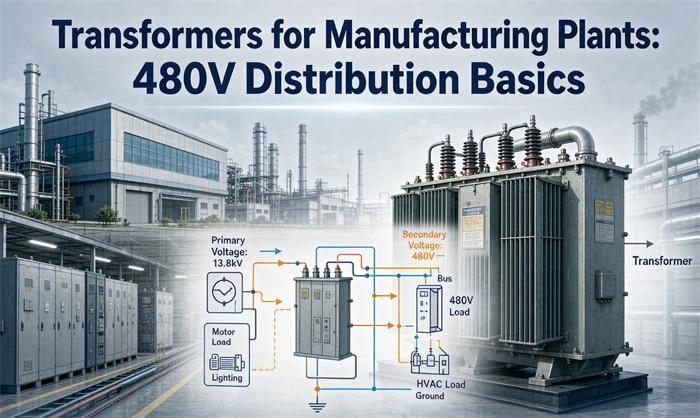
A plant’s 480V distribution is one transformer stepping the utility down to 480Y/277, a main switchboard, motor control centers for everything above 1 HP, and a smaller second transformer for receptacles and offices. The whole system sizes off one constant: 1 kVA is about 1.2 amps at 480V, three-phase.
If you already know which kVA you want and just need the machine, the 1,600 and 2,000 kVA industrial units are the usual landing spot for a plant this size. If you are still working out the architecture, that is what this page is for. It covers the four layers, the numbers each layer turns on, and the five places where plants overspend or get red-tagged.
What 480V distribution looks like inside a plant
Four layers. Most plants have all four, and only one of them needs a second transformer.
| Layer | Voltage | Typical equipment | What it feeds |
|---|---|---|---|
| Service transformer | 13.8 kV, 12.47 kV or 4.16 kV down to 480Y/277 | 500 to 2,500 kVA, oil or dry | Main switchboard |
| Main switchboard | 480Y/277, 4-wire | 1,200 to 3,000 A bus, main breaker, GFP relay | Motor control centers, 480V panelboards |
| Motor control centers | 480, 3-phase | Combination starters, soft starters, VFDs | Motors above 1 HP |
| Receptacle transformer | 480 delta down to 208Y/120 | 15 to 225 kVA dry-type | Offices, receptacles, hand tools, lighting controls |
The reason 480Y/277 is the backbone and not 208Y/120 is arithmetic. Move 500 kVA at 480V and you push 601 amps. Move the same 500 kVA at 208V and you push 1,388. Same power, 2.3 times the copper. Every footer you pour and every conduit you bend gets more expensive below 480V, which is why the low voltage only shows up at the last few hundred feet.
Why 277 volts matters more than people expect
480 divided by the square root of three is 277. That is not a coincidence or a rounding choice, it is just the line-to-neutral voltage of a wye winding. A 480Y/277 service therefore gives you two usable voltages off one set of four wires: 480 between phases for motors, 277 from any phase to neutral for lighting.
A 277V lighting circuit carries 43 percent less current than the same wattage at 120V. On a plant with 60 kW of high-bay LED, that is 216 A at 277V versus 500 A at 120V. You feel that difference in panel size, in conduit count, and in how many circuits fit in a 42-space panelboard.
The catch is that 277V is a line-to-neutral voltage on a grounded wye, so the neutral is now a current-carrying conductor with real loading on it, not a bond wire. That has consequences for the neutral bus and for ground-fault protection, both covered below.
The number worth memorizing: 1.2 amps per kVA
At 480V, three-phase, one kVA is 1.2028 amps. Round it to 1.2 and you can size almost anything in your head.
| kVA | Amps at 480V | What it typically powers |
|---|---|---|
| 75 | 90 | One department subfeed or a small press line |
| 150 | 180 | A machining cell row, four to six motors |
| 300 | 361 | One complete production line plus local HVAC |
| 500 | 601 | A mid-size line with room for a second shift |
| 750 | 902 | Roughly half a plant |
| 1,000 | 1,203 | The main for a 1 MW class site |
| 1,500 | 1,804 | A large plant with growth allowance built in |
| 2,000 | 2,406 | Heavy plant, usually bought in pairs for redundancy |
Two things this table does not show, and both bite.
Standard sizes are not continuous. The ladder is 75, 112.5, 150, 225, 300, 500, 750, 1,000, 1,500, 2,000, 2,500 kVA. Between 500 and 1,000 there is nothing. A plant that calculates 780 kVA buys 1,000, and the extra 220 kVA of core loss runs 8,760 hours a year whether or not the second shift shows up. That is why a load study is worth more than a margin.
The breaker you need may not exist in the size you calculated. Section 240.6(A) of the NEC lists the standard ampere ratings, and the gaps matter. A 300 kVA unit at 480V pulls 361 A, and 125 percent of that is 451.0 A. The standard value below it is 450 A. One ampere over, so you buy a 500 A frame. The same thing happens at 2,000 kVA: 2,406 A times 1.25 is 3,007 A, and 3,000 A is standard but 7 A short, so the next rung is 4,000 A. Two rushes of blood, two frame sizes.
Why US plants run 480V and not 400V
This section is for the buyer sourcing equipment outside North America, because the mismatch is where projects lose months.
The United States settled on 480V for industrial distribution and 460V on motor nameplates. NEMA MG-1 motors are wound for 460V because that is the utilization voltage you actually see at the terminals after feeder drop, and ANSI C84.1 Range A allows service voltage from 456 to 504 V and equipment terminal voltage from 432 to 504 V. A 460V motor on a 480V bus is inside the standard, not a compromise.
The 50 Hz trap
Here is a coincidence that helps and hurts at the same time. A 480V 60 Hz system has a volts-per-hertz ratio of 8.0. A 400V 50 Hz system also has 8.0. Same flux in the core, so the magnetic circuit of a 400V 50 Hz motor is not being over-driven when you put it on 480V 60 Hz.
But the shaft spins 20 percent faster. A 1,450 rpm machine becomes 1,740 rpm. Pumps go off their curve, fans move more air and draw more power, gearboxes and belts see a speed they were not designed for, and the driven equipment is usually the thing that fails first, not the motor.
For a new plant being built to a US spec, order 60 Hz equipment rated 460V and stop negotiating. For a plant relocating 400V machinery, put a 480 to 400V transformer in front of it, or replace the motors. A VFD is the third option and often the cheapest one, because it fixes the frequency and the voltage at the same time.
What goes on the nameplate
For a transformer feeding a US plant, the secondary should read 480Y/277, 60 Hz, with the wye solidly grounded. If the nameplate says 400Y/231, someone copied a European datasheet. The 231 is 400 divided by root three, and it will not run 277V lighting or a 460V motor properly.
480Y/277 or 480 delta? The four-wire decision
Both exist in US plants and both are legal. The choice is about what you want to feed and how much switchgear you want to buy.
| 480Y/277, 4-wire | 480 delta, 3-wire | |
|---|---|---|
| Lighting at 277V | Direct, no extra transformer | Needs a separate 480/277 or 480/208 unit |
| Neutral bus in switchboard | Required, full size | None |
| Ground-fault protection | Required at 1,000 A and above per NEC 230.95 | Not triggered by 230.95 |
| Grounding | Solidly grounded wye, one point | Ungrounded, resistance grounded, or corner-grounded |
| Harmonic path | Triplen harmonics circulate in the neutral | Delta blocks them from the primary |
| Typical use | Plants with lighting, offices, mixed loads | Motor-only MCCs, dedicated process lines |
Three practical rules.
If the plant has any 277V lighting on the 480 bus, order the wye. Adding a separate 480/277 transformer later costs more than the neutral bus did, and it takes floor space you probably do not have.
NEC 230.95 is the cost trigger. A solidly grounded wye service with more than 150 V to ground, at 1,000 A or more, must have ground-fault protection of equipment. On 480Y/277 that means 277 V to ground, which is above 150, so any main breaker at 1,000 A or larger needs a GFP relay. The setting is capped at 1,200 A with a maximum 1 second delay for faults at 3,000 A and above. Budget the relay, the sensor, and the commissioning test.
A corner-grounded delta is not a free pass. It puts 480 V on one phase to ground, which changes the insulation coordination and the marking requirements, and many maintenance electricians have never worked on one. Use it only when the process equipment requires it.
The high-leg delta warning
Older plants sometimes still run 240V center-tapped delta, where one winding is center-tapped to give 120/240 single-phase plus 240 three-phase. The center tap gives 120 V, and the opposite leg sits at about 208 V to neutral. That leg must be marked orange per NEC 408.3(E), and nothing 120V may ever be connected to it. It is one of the few wiring errors that destroys equipment instantly and starts a fire often enough to matter.
Sizing it: three methods that give three answers
Every plant engineer has seen two consultants produce two different kVA numbers for the same building. They were both right, using different methods.
Method 1, connected load times a demand factor. Add every nameplate, apply a diversity factor, divide by power factor. Fast, conservative, and it ignores how the plant actually runs. On a plant with 2,050 A of connected load at a 0.75 factor, you get about 1,540 A.
Method 2, the NEC motor method. Section 430.24 sizes a feeder for multiple motors as 125 percent of the largest motor full-load current plus 100 percent of all the others, then add the non-motor loads. It is not a diversity calculation, it is a minimum, and it is what the inspector will check.
Method 3, twelve months of metered demand. If the plant exists, the utility bill has the answer. Take the peak demand in kW, divide by the operating power factor, and you have the real kVA. Nothing else comes close for accuracy.
A worked example
A stamping and assembly plant, 480Y/277 service, existing building being rewired.
| Load group | Detail | Amps at 480V |
|---|---|---|
| Largest motor | 1 × 250 HP, 302 A per Table 430.250 | 302 |
| Other large motors | 2 × 100 HP at 124 A | 248 |
| Medium motors | 6 × 30 HP at 40 A | 240 |
| Small motors | 10 × 10 HP at 14 A | 140 |
| 277V high-bay lighting | 60 kW, continuous | 180 |
| Process heating | Resistance banks | 200 |
| Welding | Intermittent, 2 units | 100 |
Apply 430.24 to the motor group: 302 times 1.25 is 377.5, plus 248, 240 and 140 gives 1,005.5 A. Lighting is a continuous load, so 180 times 1.25 is 225. Heating and welding add at 100 percent, 300 A.
Total: 1,530.5 A. Multiply by 1.732 and by 480, divide by 1,000: 1,272 kVA.
The standard size above that is 1,500 kVA, which runs at 85 percent of nameplate at peak. That is a healthy landing spot.
Now the growth question. The plant expects to add a third shift and one more press line inside five years, roughly 20 percent. 1,272 times 1.20 is 1,526 kVA. The 1,500 kVA unit no longer covers it.
That leaves three honest answers, and none of them is “buy 2,000 kVA and relax”:
- Buy 1,500 kVA now and plan a second 750 kVA unit for the expansion. Two units give you maintenance isolation, which a single 2,000 kVA unit cannot.
- Buy 2,000 kVA now at 64 percent initial loading and accept the extra no-load loss until the load arrives.
- Buy 1,500 kVA now, run the expansion on a VFD-driven line with a lower starting demand, and revisit in year four.
The single-versus-multiple decision is usually settled by downtime cost, not by price per kVA. A plant that loses $40,000 an hour cannot afford one transformer, no matter how efficiently it runs.
Protecting it: NEC 450.3(B) in one table
Article 450 gives you two options. Protect the primary only, or protect both sides. The table below is the 480V primary case, with the 240.6(A) rounding already applied.
| kVA | FLA at 480V | 125% (both sides) | Next standard | 250% (primary only) | Next standard |
|---|---|---|---|---|---|
| 300 | 361 | 451.0 | 500 A | 902 | 1,000 A |
| 500 | 601 | 751.7 | 800 A | 1,503 | 1,600 A |
| 750 | 902 | 1,127.6 | 1,200 A | 2,255 | 2,500 A |
| 1,000 | 1,203 | 1,503.5 | 1,600 A | 3,007 | 4,000 A |
| 1,500 | 1,804 | 2,255.3 | 2,500 A | 4,510 | 5,000 A |
| 2,000 | 2,406 | 3,007.0 | 4,000 A | 6,014 | Above the standard list |
The 2,000 kVA row is the one to notice. At 250 percent you are at 6,014 A, and 6,000 A is the top of the standard rating table. Past that point the primary-only option stops being practical and you protect both sides.
Three things the table does not say, and the inspector will.
Primary-only protection does not exempt the secondary conductors. Section 240.21(C) still governs how far those conductors can run before they need their own protection. On a 480 to 208/120 transformer feeding a panel 40 feet away, that tap rule is what decides the layout.
The 125 percent column is for the transformer, not the load. OCPD sizing protects the winding. The feeder ampacity is a separate calculation under 215.2 and it uses the load, not the nameplate.
Wye secondaries create separately derived systems. Section 250.30 applies, which means a system bonding jumper and a grounding electrode conductor at the transformer, not at the service. Getting this wrong is a common finding on a first inspection, and it is invisible until someone tests it.
Fault current and SCCR: the label most plants fail
This is where manufacturing plants differ most from commercial buildings, and it is the single most expensive thing to fix after the fact.
Available fault current on the 480V bus comes from two sources: the transformer, and every motor already spinning.
Transformer contribution is full-load current divided by per-unit impedance. A 1,000 kVA unit at 5.75 percent impedance delivers 1,203 divided by 0.0575, which is 20.9 kA.
Motor contribution is the part people forget. Running induction motors act as generators for the first few cycles of a fault. Add roughly four times the total running motor current: 930 A of motors contributes about 3.7 kA.
Total: 24.6 kA at the main bus, before you count any diversity.
That number rules out 22 kA switchgear, which is the default catalog rating most people reach for. A 22 kA panelboard installed on a 24.6 kA bus is a violation of NEC 110.10, and the label required by 409.110 has to state the short-circuit current rating honestly. Order 65 kA for a plant of this size and stop thinking about it. The price difference on the gear is small compared to replacing it after a failed inspection.
Two details that catch people:
Impedance tolerance runs the wrong way. A unit built a few percent below nominal impedance pushes fault current up, not down. At 1,000 kVA you need at least 5.47 percent impedance to stay under 22 kA, and units are routinely built under nominal. Design at the low end of the tolerance band.
Small transformers are not automatically safer. A 75 kVA unit at 4 percent impedance delivers 90 divided by 0.04, or 2,255 A. That is fine on its own, but it sits downstream of a bus that already has 24.6 kA available.
Voltage drop and motor starting
Two calculations decide cable size and starting method, and neither is in Article 450.
Voltage drop. The industry convention is 3 percent total on a feeder plus branch circuit, which at 480V is 14.4 volts. Using copper resistance at 75 degrees C and a 400 A load:
| Conductor | Ohms per 1,000 ft | Volts lost per 100 ft | Feet to 3 percent |
|---|---|---|---|
| 3/0 AWG | 0.0766 | 5.31 | 271 |
| 250 kcmil | 0.0515 | 3.57 | 404 |
| 500 kcmil | 0.0258 | 1.79 | 806 |
| 750 kcmil | 0.0171 | 1.18 | 1,215 |
Resistance only. On feeders above 250 kcmil, reactance adds another 10 to 20 percent, so treat these as the optimistic end.
The useful comparison is what happens when you drop a voltage level. Move that same 400 A load to a 208V secondary and the allowable drop halves while the current goes up 2.3 times. The 806 feet becomes roughly 150 feet. This is the real argument for keeping 480V as far into the plant as you can and dropping to 208/120 only at the point of use.
Motor starting. A large motor starting across the line looks like a momentary short to the transformer. The voltage dip is approximately the starting kVA divided by the transformer kVA, times the impedance.
A 250 HP motor draws 302 A running and about 1,812 A locked rotor, roughly six times. Starting kVA is 1,506.
| Transformer | Voltage dip starting that motor |
|---|---|
| 500 kVA | 17.3 percent |
| 1,000 kVA | 8.7 percent |
| 1,500 kVA | 5.8 percent |
| 2,000 kVA | 4.3 percent |
NEMA MG-1 expects a motor to start at 80 percent of rated terminal voltage, so a 17.3 percent dip is technically survivable. But contactors drop out around 70 percent, and VFDs on the same bus fault on dips well above that. On a plant with drives, keep the dip under 10 percent, which means either a bigger transformer or a soft starter. A soft starter costs a fraction of the transformer step.
VFD harmonics: how much K-factor you actually need
A plant full of drives can run a transformer hot while a clamp meter reads well under nameplate. Harmonic currents heat windings in proportion to frequency squared, so the fifth harmonic does far more damage than its amplitude suggests.
| K-factor | Derating factor | Load mix |
|---|---|---|
| K-1 (standard) | 1.00 | Linear loads only, no drives |
| K-4 | 0.96 | Scattered drives, mostly motors on starters |
| K-13 | 0.88 | Drive-heavy line, UPS, LED drivers on the same bus |
| K-20 | 0.84 | SCR drives, induction heating, rectifiers |
Two things people get wrong. A K-rated transformer tolerates harmonics, it does not remove them. And the K-factor and the ambient derating stack, they do not replace each other. A K-13 unit in a 40 degree C electrical room with poor ventilation is still derated twice.
The cheap answer for most plants: specify K-13, tell the manufacturer the drive count and the expected THD, and confirm the quoted kVA already accounts for harmonic duty. If they cannot state the assumption, that is your answer about the quote.
Dry-type or oil, and what to put on the RFQ
The indoor decision is mostly code-driven. An oil-filled transformer inside a building needs a vault with fire-rated construction under Article 450, which costs more than the transformer. A dry-type unit in the same room does not. That is why the 480 to 208/120 transformer in the electrical room is almost always cast resin, and the 13.8 kV service unit sitting on a pad outside is almost always oil.
For the full comparison including loss economics and maintenance intervals, the oil-immersed versus dry-type breakdown covers it. For a plant that needs dry-type for indoor siting, the Grade 1 cast resin units from 30 to 5,000 kVA meet the DOE efficiency floors without a vault.