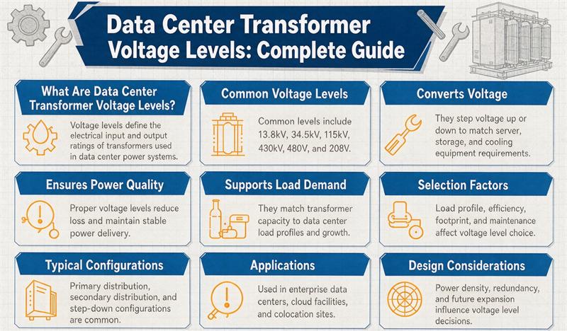
Data center transformers step utility power down through three voltage tiers: utility interconnect at 115–345 kV, medium-voltage distribution at 13.8–34.5 kV (10–20 kV across most of Europe), and low-voltage IT distribution at 480 V / 208–120 V (400 V / 230 V in Europe), so every server rack gets clean, usable power. This guide breaks down each tier, explains why those numbers are what they are, shows how North American and European sites differ, and gives you a copy-paste RFQ checklist.
If you are speccing a facility right now, the voltage question shows up early and it is surprisingly easy to get wrong. Pick the wrong tier and you either overspend on switchgear or quietly strangle your own redundancy. The short version is simple: power comes in from the utility at transmission voltage, drops to medium voltage for the campus, then drops again to low voltage at the rack. Everything in between is about moving that energy safely, efficiently, and without a single point of failure.
We at TransNine Electric build units for all three tiers, and the same questions come from buyers on both sides of the Atlantic. So this is written for the person actually placing the order, not for an IEEE textbook.
Why Voltage Levels Decide Everything Else
Before the numbers, here is the why. Transformer voltage levels are not arbitrary. They lock in four things at once:
- Uptime. Each step-down is a place where a redundant feed (N+1 or 2N) has to be planned. Get the tier wrong and you cannot route an independent A/B path.
- Efficiency. Every conversion loses a little energy as heat. Fewer, cleaner steps keep your PUE down.
- Fire safety and code. Indoor low-voltage rooms have hard rules about oil. That pushes you to dry-type units in specific tiers.
- Cost. Medium-voltage switchgear and cabling are far cheaper per amp than low-voltage. Step down too late and your copper bill explodes.
That is the whole game. Now the tiers.
The Three Voltage Tiers
Every modern data center, from a 200 kW edge site to a 200 MW hyperscale campus, runs the same three-layer ladder. The voltages below are the ones you will actually see on a single-line diagram.
| Tier | What it does | North America | Europe | Typical size | Common type |
|---|---|---|---|---|---|
| 1. Utility interconnect | Grid to campus | 115 / 138 / 230 / 345 kV | 110 / 220 / 400 kV | 30–300+ MVA | Substation-class, oil or dry |
| 2. MV distribution | Campus to hall | 13.8 / 34.5 kV | 10 / 20 kV | 2–15 MVA | Pad-mount or cast-resin dry-type |
| 3. Low-voltage IT | Hall to rack | 480 V, then 208 / 120 V | 400 V, then 230 V | 500–2,500 kVA | Dry-type, K-13 / K-20 |
Tier 1 is the utility connection. You do not choose this voltage; your local grid does. Tier 2 is where the campus distributes power to individual buildings or halls. Tier 3 is the final drop that feeds the PDUs and racks inside the white space.
Want the full range of hardware that covers all three? Browse our transformer catalog to see what sits at each level.
Why These Exact Numbers
People ask why we do not just run one big step from the grid straight to 480 V. Two reasons.
First, the utility interconnect voltage is fixed by the transmission line at your interconnect point. In US grids, 138 kV is common in PJM and MISO, 138 or 230 kV in ERCOT, and 230 or 345 kV in WECC. In Europe, 110 kV is typical for regional supply and 220 or 400 kV for backbone interconnections. You take what the grid gives you.
Second, medium voltage exists to cut losses. Power loss in a cable scales with current squared (I²R). Push the same watts at 13.8 kV instead of 480 V and your current drops by roughly 29 times, which slashes both conductor size and heat loss across the campus. That is why every campus distributes at 13.8 or 34.5 kV (10 or 20 kV in Europe) and only steps to low voltage right where the IT load lives.
A quick feel for scale: a 30 MW IT campus runs about 45 MW of total facility load once you add PUE, losses, and cooling. That single campus might hang off two 50 MVA substation transformers, feed a dozen 5–12 MVA distribution units, and finish with scores of 750–2,500 kVA dry-type units at the racks.
The Power Chain, Node by Node
Here is the electrical path with the voltage at every handoff. This is the chain Google and your EPC both expect to see:
- Utility grid at 115–345 kV (NA) or 110–400 kV (EU).
- MV switchgear at the same utility voltage.
- MV transformer steps down to 13.8 / 34.5 kV (NA) or 10 / 20 kV (EU).
- UPS system sits on that medium voltage or just below it.
- PDU transformer drops to 480 V (NA) or 400 V (EU), then to 208 / 120 V or 230 V at the branch.
- Server rack draws the final low-voltage power.
Each transformer in that chain is doing a different job. The substation unit handles bulk energy and needs online monitoring. The distribution unit feeds a whole hall. The PDU unit lives next to the racks and has to swallow harmonic distortion from all those server power supplies.
If you want a purpose-built path through tiers 2 and 3, our data center transformer solutions package the MV drop and the LV drop as one coordinated design.
North America vs Europe
This is the part most guides skip, and it matters because your buyers are on both continents. The function is identical. The numbers are not.
| Element | North America | Europe |
|---|---|---|
| Utility interconnect | 115 / 138 / 230 / 345 kV | 110 / 220 / 400 kV |
| MV distribution | 13.8 / 34.5 kV | 10 / 20 kV |
| Low-voltage main | 480 V (277 V line-neutral) | 400 V (230 V line-neutral) |
| Rack voltage | 208 / 120 V | 230 V |
| Frequency | 60 Hz | 50 Hz |
| Key standards | IEEE C57, NEC 450, NFPA 75/76, UL 1561/1562 | IEC 60076-11, EU EcoDesign, EN 50588 |
The 480 V versus 400 V split is the big one. North American IT gear is built around 208 V three-phase from a 480 V bus. European and most IEC-market gear runs on 400 V three-phase with 230 V line-to-neutral. Same servers, different nameplate. Frequency (60 vs 50 Hz) changes nothing about the voltage tiers but it does change core and fan calculations, so never forget to state it on the RFQ.
Dry-Type vs Oil at Each Tier
A question we get constantly: dry or oil? The honest answer is it depends on where the unit sits.
- Tier 1 substation: almost always oil-immersed, outdoors, with containment. The size and cooling demand make oil the only practical choice.
- Tier 2 distribution: either pad-mount oil outdoors or cast-resin dry-type indoors, depending on layout and local fire code.
- Tier 3 IT distribution: dry-type, full stop, when it is inside the building. NEC 450 and NFPA 75/76 restrict liquid-filled units inside the envelope unless you build containment and fire suppression around them. Dry-type with an F1 fire behavior class (per IEC 60076-11) just complies.
Our cast-resin dry-type units are built exactly for that tier 2 and tier 3 indoor job: self-extinguishing, low maintenance, and happy sitting close to the load with no oil pit.
Harmonics and K-Rating at the Low-Voltage Level
Server power supplies are nasty loads. They are non-linear, which means they pump harmonic current back into the transformer. Left alone, that extra heating quietly shortens the life of a standard unit.
The fix is a K-rated dry-type transformer. K-13 handles typical UPS and rack loads. K-20 covers the heavier harmonic content you see in AI and GPU halls. You also want an oversized neutral conductor, because those same harmonics pile up in the neutral. Specifying K-13 or K-20 at the 480 V (or 400 V) secondary is one of the cheapest insurance policies in the whole build.
We shipped K-factor dry-type transformers we built for a hyperscale data centre exactly for this reason, and the harmonic margin was the spec that mattered most to the buyer.
How to Size the Transformers
Here is the part you can actually use. Sizing is just three multiplications. Do them in order.
- Take your critical IT load in kW and multiply by 1.5. That covers PUE, losses, and cooling. Result: total facility kW.
- Divide by your power factor, usually 0.95. Result: required transformer kVA at the point of use.
- Multiply by the redundancy factor: 1.33 for N+1, 2.0 for 2N. Result: installed transformer kVA.
Worked example: 30 MW IT load times 1.5 equals 45 MW facility. Divide by 0.95 equals about 47.4 MVA required. With 2N redundancy that is roughly 95 MVA installed, which on a real campus becomes eight 12 MVA distribution transformers in two paths, fed by two 50 MVA substation units.
The math is the same in Europe. Only the voltage and frequency inputs change.
Standards Buyers Should Know
You do not need to memorize these, but they should appear somewhere in your spec sheet:
- IEEE C57.12.01 (dry-type general requirements) and the IEEE C57 series for North America.
- IEC 60076-11 for dry-type construction and fire behavior (F0 / F1 / F2).
- DOE 2016 efficiency rules, with DOE 2027 tightening them from January 1, 2027. If your energization date is 2027 or later, spec the newer tier now.
- EU EcoDesign Tier 1 (loss limits) and Tier 2 (premium efficiency) for anything serving the European market.
- NFPA 75 / 76 and NEC 450 for indoor fire safety in the US.
- UL 1561 / 1562 for liquid-filled and dry-type listing.
Our technical resource library walks through nameplate reading, routine testing, and the IEC vs ANSI standard split if you want the deeper version.
Lead Times and Your RFQ Checklist
Transformer delivery is the critical path on most 2026 and 2027 builds. Substation-class units from tier-1 OEMs are quoting 128–200+ weeks. More nimble suppliers run 32–48 weeks for substation and 14–22 weeks for distribution. Order the substation unit within about 4 months of site selection, and distribution units no later than 6 months before energization.
When you send the RFQ, include these lines so the factory can size correctly:
- Critical IT load (kW) and target PUE
- Utility interconnect voltage and frequency (50 or 60 Hz)
- Required redundancy: N, N+1, or 2N
- MV distribution level (13.8 / 34.5 kV, or 10 / 20 kV for Europe)
- LV level (480/208 or 400/230)
- K-rating (K-13 or K-20) and harmonic content
- Efficiency tier (DOE 2016/2027 or EcoDesign Tier 1/2)
- Dry-type or oil, and indoor/outdoor placement
- Relevant standards (IEEE C57, IEC 60076-11, UL, NFPA)
You can see how these specs played out in real builds across our project case studies, from hospitals to metro traction to hyperscale data halls.
Frequently Asked Questions
What voltage do data center transformers use?
Data center transformers operate across three tiers: utility interconnect at 115–345 kV (North America) or 110–400 kV (Europe), medium-voltage distribution at 13.8–34.5 kV (10–20 kV in Europe), and low-voltage IT distribution at 480 V / 208–120 V (400 V / 230 V in Europe).
What is the most common medium-voltage level in US data centers?
13.8 kV is the workhorse for hall distribution, with 34.5 kV used on larger campuses to cut losses over longer runs. Both step down from the utility interconnect.
Why 480 V and not 208 V at the main distribution?
480 V is the efficient building-level bus. You only drop to 208 / 120 V at the PDU and rack, because running the whole facility at 208 V would mean much higher currents and far more copper.
What voltage do European data centers use?
European sites distribute at 10 or 20 kV medium voltage and deliver 400 V three-phase (230 V line-to-neutral) at the rack. Frequency is 50 Hz rather than 60 Hz.
Do data centers use dry-type or oil transformers?
Oil-immersed units dominate the outdoor substation tier. Indoors, especially near the IT load, dry-type (often cast-resin) is the default because fire codes like NEC 450 and NFPA 75/76 restrict liquid-filled units inside the building envelope.
How big is a data center transformer, in kVA or MVA?
It spans a huge range by tier: 500–2,500 kVA for low-voltage IT units, 2–15 MVA for hall distribution, and 30–300+ MVA for the utility interconnect substation.
How do I specify voltage levels in an RFQ?
State the utility voltage and frequency, the MV distribution level, the LV level, redundancy (N / N+1 / 2N), K-rating, efficiency tier, dry or oil placement, and the applicable standards. The checklist above covers every line.