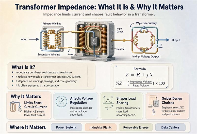
A transformer’s impedance, printed on the nameplate as %Z, is the percentage of rated voltage you must apply to a shorted winding to drive full-load current through it. It is the single number that decides how much fault current can flow, how far the voltage sags under load, and how evenly two units in parallel share the work. If you only learn one parameter on a transformer, make it this one.
We build dry-type and oil-immersed units at TransNine Electric every week, and the first question our North American and European buyers ask is almost never “what is impedance.” It is “will this number let my breaker clear a fault, and will my motor still start.” That is the practical angle this guide takes. You can browse the full product range or jump to the resources hub for the rest of our buyer guides.
What Transformer Impedance Actually Is
Impedance is the transformer’s internal opposition to alternating current. On paper it is one number, %Z, but inside the tank it comes from two physical sources:
- Resistance (R): the heating loss in the copper windings.
- Reactance (X): mainly leakage reactance, caused by the magnetic flux that escapes the core and links only one winding.
In almost every power and distribution transformer, X is far larger than R. A 1000 kVA unit might show R around 1 percent and X around 5.6 percent, which rolls up to about 5.7 percent total impedance. So when someone says “the impedance is 5.75 percent,” they are really talking about leakage reactance dressed up as a percentage.
The formal definition comes from the short-circuit test. You short one winding, apply a reduced voltage to the other, and raise it until rated current flows. The voltage you needed, expressed as a percentage of rated voltage, is the impedance. The formula is dead simple:
%Z = (Vsc / Vrated) × 100
If a 10 kV winding needs 600 V to push rated current through a shorted low-voltage side, the impedance is 600 / 10000 × 100 = 6 percent. That is the whole idea.
The Worked Example You Can Verify Yourself
Numbers stick better when you can check them. Take a common North American unit:
- Rating: 1000 kVA, three-phase
- Primary-secondary: 480 V
- Nameplate impedance: 5.75 percent
Step 1, find the full-load current. For a three-phase transformer, I = kVA × 1000 / (√3 × V). So 1000 × 1000 / (1.732 × 480) = 1,202.8 A. Write that down: this transformer carries about 1203 amps at full load.
Step 2, find the terminal fault current. When the secondary is bolted short, the only thing limiting current is the transformer itself, so:
Isc ≈ Irated / Z(pu)
Z as a per-unit decimal is 0.0575. So Isc ≈ 1202.8 / 0.0575 = 20,918 A, or about 20.9 kA. Do the division on your phone; it lands in the same place. That 20.9 kA is the number your switchgear and breakers must survive. Add the utility source behind the transformer and the real fault current is a bit higher, which is exactly why protection studies never stop at the nameplate.
Why Impedance Matters: The Three Jobs
Everything else about %Z flows from three jobs it does in your system.
1. It caps the fault current (the one buyers feel)
Fault current is roughly the rated current divided by the per-unit impedance. Because the relationship is inverse, small changes in %Z move the fault level a lot. Here is the quick reference:
| Nameplate %Z | Fault current as a multiple of rated |
|---|---|
| 4% | about 25 times |
| 5% | about 20 times |
| 5.75% | about 17.4 times |
| 6% | about 16.7 times |
| 8% | about 12.5 times |
| 10% | about 10 times |
A lower impedance means a nastier fault. That touches NEC 450.3(B) for overcurrent protection and NEC 110.10, which says you must limit fault current so equipment can safely interrupt it. Pick %Z too low and you may be forced into costlier 65 kA or 85 kA rated gear. Pick it too high and you trade that problem for the next one.
2. It sets the voltage drop under load
Impedance is also the voltage you lose as load climbs. A higher %Z gives a bigger sag between no-load and full-load voltage, and the effect worsens with a lagging (inductive) power factor. In a plant with large motors, a transformer with too much impedance can make the lights dim and the drives trip when a big motor starts. Voltage regulation is usually written as:
VR% = (Vnl − Vfl) / Vfl × 100
Lower impedance holds the voltage steadier, which is why data centers and sensitive commercial loads lean toward the low end of the typical range. Our data-center calculator sizes units with that stiffness in mind.
3. It decides how parallel units share load
Run two transformers in parallel and they must have nearly the same %Z, the same voltage ratio, and the same vector group. If one is 5 percent and the other is 8 percent, the lower-impedance unit grabs the larger share of the current and can overload while its partner loafs. Even at no load, a mismatch can circulate current between the two and bake extra losses into the system. Matching impedance is not a nicety; it is a parallel-operation requirement.
Typical Impedance by Application
These are typical starting points, not guarantees. Confirm the exact value against your specification and the nameplate.
| Application | Typical %Z range |
|---|---|
| Low-voltage distribution (up to 600 V) | 2% to 6% |
| Medium-voltage dry-type (2.4 to 35 kV) | 4% to 8% |
| Pad-mounted and submersible | 4% to 5.75% |
| Power and network (transmission class) | 8% to 15% |
| Generator step-up (GSU) | 10% to 18% |
| Arc-furnace transformers | above 15% |
| Auto-transformers | usually lower, by design |
Notice the pattern. Distribution wants low impedance for tight voltage. Transmission and generation accept higher impedance because the fault levels are enormous and limiting current protects the whole network.
The X/R Ratio Buyers Forget
%Z is mostly reactance, but the nameplate also lists X/R, the ratio of reactance to resistance. This matters because a fault current is not a clean sine wave at the first instant. The DC offset decays over time, and a high X/R means that offset lasts longer and the first-cycle (momentary) current peaks higher relative to the steady (symmetrical) value. Breakers are rated on symmetrical amperes, so a high X/R can quietly push you into a bigger interrupting class. If your protection engineer asks for X/R, they are checking whether the breaker can actually clear the fault, not just whether %Z looks right.
Lower vs Higher: The Real Trade-off
A common myth says “lower impedance is always better.” It is not. Lower impedance gives better voltage regulation but a harder fault. Higher impedance tames the fault but sags the voltage and can starve motor starting. The right value is a balance set by your system, not a race to the bottom.
| If you choose lower %Z | If you choose higher %Z |
|---|---|
| Tighter voltage regulation | More fault-current headroom |
| Smaller voltage sag on motor start | Bigger voltage drop under load |
| Higher available fault current | Possible voltage complaints from loads |
| Costlier breakers and switchgear | Cheaper protection ratings possible |
The answer is found by running the fault study and the voltage-drop study together, then reading the project specification.
How Impedance Is Set in the Factory
Impedance is not a dial you turn. It is mostly leakage reactance, and leakage reactance is set by the physical spacing between windings and the winding geometry. Pull the windings farther apart and %Z goes up; couple them tighter and it comes down. That spacing also changes the mechanical size and the copper needed, so impedance is tied to cost and footprint from the drawing stage.
Because it is baked into the design, the tolerance matters more than buyers expect. IEEE C57 allows about ±10 percent on the tested value; IEC 60076-1 tightens that to about ±7.5 percent for most units. A delivered unit that drifts past tolerance can fail acceptance and, worse, can wreck a parallel bank’s load sharing. Treat the tolerance as a real acceptance criterion, not fine print.
Reading %Z on the Nameplate
When you flip the nameplate, look for these near each other:
- %Z or Zk: the short-circuit impedance, our headline number.
- X/R: the reactance-to-resistance ratio, your fault-clearing clue.
- Voltage and kVA the %Z was measured at: impedance is quoted at a specific rating, so match it to your operating point.
If the supplier only hands you a brochure number and no test certificate, that is a flag. Ask for the routine-test report; impedance is one of the values every unit should pass before it ships.
Standards You Will Cite
Keep these on hand when you write the specification or review a submittal:
- IEEE C57.12.00 and C57.12.90: general requirements and the test method for impedance.
- IEC 60076-1: the international general-requirements equivalent, with the ±7.5 percent tolerance.
- NEC Article 450: transformers and overcurrent protection, including 450.3(B).
- NEC 110.10: requires fault-current limitation so equipment can interrupt safely.
For total-cost thinking, our loss and TCO calculator shows how impedance-related load losses compound over 30 years, and the NEC calculator turns %Z into the fault current your gear must handle.
Buyer’s Checklist (the numbers that matter)
Before you release a purchase order, confirm these:
- Nameplate %Z and the tolerance band (±7.5% IEC or ±10% IEEE).
- Calculated terminal fault current from Isc ≈ Irated / Z(pu), then add the source.
- Breaker and switchgear interrupting rating sized above that fault current (NEC 450.3, 110.10).
- Voltage drop at your worst-case load and power factor.
- X/R ratio for first-cycle and interrupting-class checks.
- For parallel banks, matched %Z within the tolerance, same ratio, same vector group.
- Routine-test certificate showing the measured impedance, not just a brochure claim.
Common Myths, Cleared Up
- “Lower impedance is always better.” False. It trades voltage regulation for fault severity.
- “Impedance is just resistance.” False for practical purposes; it is mostly leakage reactance.
- “You can adjust impedance in the field.” No. It is fixed by winding geometry at the factory.
- “Impedance does not affect losses.” Not quite; higher leakage reactance usually means higher load losses for a given rating.
Where It Shows Up in Real Projects
Impedance is not academic. A hyperscale data center wants a stiff bus, so the units run low %Z to hold voltage under sharp IT load swings. A 50 MW solar plant’s step-up transformers must be specified so the fault current stays inside the inverter and pad-mount protection ratings. An arc-furnace installation deliberately runs high impedance to stabilize the arc and protect the network. You can see how we handle these in our project archive, from low-noise hospital dry-type units to utility-scale solar step-ups.
Wrapping Up
Transformer impedance, %Z, is the quiet parameter that decides whether your system is safe, stable, and shareable. It caps fault current, sets voltage drop, and governs parallel load sharing, and it is fixed by the factory geometry rather than tuned in the field. Read it off the nameplate, check the X/R, run the fault and voltage-drop studies, and confirm the tolerance on the test report. Do those things and impedance stops being mysterious and starts being the most useful number on the plate.
FAQ
What is transformer impedance in simple terms? Transformer impedance, written as %Z, is the percentage of rated voltage needed on one winding to push full-load current through the other winding when it is shorted. It tells you how strongly the transformer resists sudden current surges.
How do you calculate the fault current from %Z? Use Isc ≈ Irated / Z(pu), where Z(pu) is the percent impedance as a decimal. For a 1000 kVA, 480 V unit at 5.75 percent, the full-load current is about 1203 A and the terminal fault current is about 20.9 kA.
What is a typical transformer impedance value? Low-voltage distribution units typically run 2 percent to 6 percent. Medium-voltage dry-type units run 4 percent to 8 percent. Transmission and generator step-up units run 8 percent to 18 percent, and arc-furnace units often exceed 15 percent.
What does X/R ratio mean on a transformer nameplate? X/R is the ratio of reactance to resistance. Because impedance is mostly reactance, a high X/R means the fault current’s DC offset lasts longer, which raises the first-cycle peak and can push you into a higher breaker interrupting class.
Is lower impedance always better? No. Lower impedance improves voltage regulation but allows higher fault current, which forces costlier protection gear. Higher impedance limits faults but increases voltage drop. The right value comes from a fault and voltage-drop study plus the project specification.
What impedance tolerance is allowed? IEEE C57 allows about ±10 percent on the tested impedance, while IEC 60076-1 allows about ±7.5 percent for most units. Mismatched or out-of-tolerance impedance can ruin parallel load sharing and fail acceptance.
Can impedance be changed in the field? No. Impedance is set by winding geometry and the spacing between windings at the factory. It cannot be adjusted on site, which is why it is a design and acceptance parameter, not a field setting.
Which standards cover transformer impedance? IEEE C57.12.00 and C57.12.90 cover the requirements and test method, IEC 60076-1 is the international equivalent, and NEC Article 450 plus 110.10 govern overcurrent protection and fault-current limitation in North American installations.