- Capacity: 15–31500 kVA
- Voltage: 6 / 11 / 20 kV
- Tap changer: on-load (OLTC)
- Cooling: ONAN
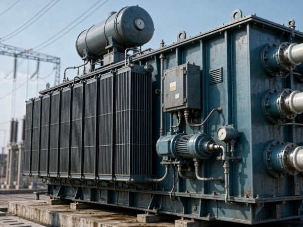
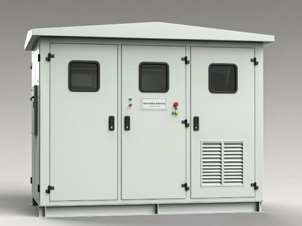
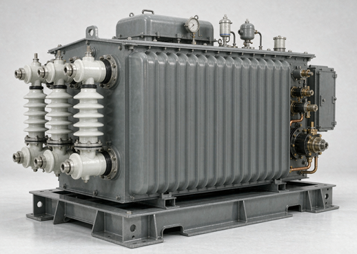
The SZ11 Series is a three-phase, oil-immersed power transformer equipped with an On-Load Tap Changer (OLTC) that enables voltage regulation without interrupting the load supply. Designed for 35 kV class distribution and sub-transmission networks, this transformer dynamically adjusts its turns ratio to maintain stable secondary voltage as primary voltage or load conditions fluctuate. This capability is increasingly critical for U.S. utilities and industrial operators navigating the voltage volatility introduced by renewable integration, electric vehicle charging, and data center loads.
The SZ11 is engineered for continuous duty in substation, industrial plant, and renewable energy collector applications. Its tap changer allows operators to correct voltage deviations in real time — a decisive advantage over offline tap-changing designs that require de-energization and manual adjustment.
How It Works: The On-Load Tap Changer Advantage
Traditional distribution transformers use off-circuit tap changers that can only be adjusted when the transformer is de-energized. The SZ11’s OLTC eliminates this limitation. The tap changer is integrated into the high-voltage winding and operates through a motor-driven mechanism that selects different winding taps while the transformer remains energized and loaded.
The OLTC operates through a diverter switch and selector switch assembly. The selector switch chooses the appropriate tap on the high-voltage winding, while the diverter switch performs the actual transition under load using transition resistors to limit circulating current during the bridging state. This mechanical sequence completes in milliseconds and is designed for thousands of operations.
The tap range for the SZ11 is typically ±3 × 2.5% (seven positions) or ±8 × 1.25% for wider regulation applications. Each tap step changes the transformer ratio by a defined increment, allowing precise voltage correction across a range of approximately ±7.5% to ±10% from nominal.
Why This Matters for U.S. Grid Operators
Renewable Integration and Voltage Fluctuation
The rapid growth of distributed energy resources — particularly solar PV and wind — has transformed U.S. distribution networks from passive, unidirectional systems into active, bidirectional grids. Solar generation peaks during midday when load is often moderate, causing voltage rise on feeders. Conversely, cloud transients create rapid voltage sags. The SZ11’s OLTC responds to these fluctuations by adjusting tap position automatically or on command, keeping secondary voltage within ANSI C84.1 Range A limits.
Research confirms that OLTC technology remains a cost-effective and mature solution for voltage regulation in high-penetration renewable scenarios. By dynamically adjusting the transformation ratio, OLTC-equipped transformers effectively mitigate voltage violations and enhance the grid’s hosting capacity for new energy sources.
Load Growth and Grid Stress
U.S. utilities face unprecedented load growth from data centers, AI compute facilities, and transportation electrification. The DOE has noted that distribution transformer lead times now exceed 30 months, driven by surging demand and supply chain constraints. Deploying OLTC-equipped transformers like the SZ11 maximizes the utilization of existing grid infrastructure by providing flexible voltage support without requiring capacitor bank switching or reconductoring.
Regulatory Landscape
The SZ11 design aligns with U.S. market requirements including DOE energy conservation standards (10 CFR Part 431) and IEEE C57 series standards for power transformers. For federally funded infrastructure projects, the Build America, Buy America Act (BABA) domestic content requirements apply — NEMA’s Make It American™ certification program now includes high- and medium-voltage distribution equipment, providing third-party verification of domestic manufacturing compliance.
Technical Specifications
| Parameter | Typical Range |
|---|---|
| Rated Capacity | 2,000 – 31,500 kVA |
| Primary Voltage | 35 kV, 38.5 kV (35–38.5 kV range) |
| Secondary Voltage | 6.3 kV, 6.6 kV, 10.5 kV |
| Tap Range | ±3 × 2.5% (standard) or ±8 × 1.25% |
| Connection Symbol | Yd11, YNd11 |
| Impedance | 6.5% – 10.0% (varies by rating) |
| No-Load Loss | Optimized for SZ11 efficiency tier |
| Cooling | ONAN (Oil Natural Air Natural) |
| Insulation Class | Class A (oil-immersed) |
| Standards | IEC 60076, GB 1094, ANSI/IEEE C57 |
Parameter values vary by specific rating. Consult the factory for exact data on your required kVA and voltage combination.
Key Design Features
High-Grade Core Construction. The core uses cold-rolled grain-oriented silicon steel (GOES) with 45° miter joints and epoxy-bound laminations. This construction minimizes no-load loss and noise while ensuring mechanical integrity under short-circuit forces.
Optimized Insulation System. The new insulation structure improves heat dissipation from windings to oil, reducing temperature rise and extending insulation life. The oil tank employs a corrugated or fully sealed design that prevents oil contact with air and moisture, slowing oil aging and reducing maintenance intervals.
Pressure Relief Protection. A pressure relief valve is installed on the tank to safely release internal pressure in the event of an internal fault, preventing catastrophic tank rupture.
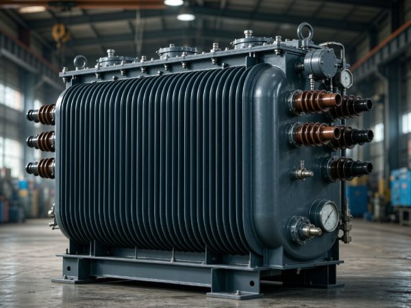
Corrugated Tank Design. The corrugated sheet wall accommodates oil thermal expansion and contraction through elastic deformation, eliminating the need for a separate conservator in smaller ratings and reducing the transformer’s footprint.
Typical Applications
-
Utility Substations: Voltage support at 35 kV sub-transmission and distribution substations, particularly where feeder voltage profiles vary with load.
-
Industrial Plants: Large manufacturing facilities with sensitive processes requiring stable voltage despite upstream grid fluctuations.
-
Renewable Energy Collector Substations: Solar and wind farms where output variability causes voltage excursions on the collector system.
-
Data Centers: Facilities with high-density, constant-power loads that require tight voltage regulation and cannot tolerate supply interruption.
-
Electric Vehicle Charging Hubs: High-power charging stations where rapid load changes stress local voltage regulation.
Frequently Asked Questions
Q: How does an on-load tap changer differ from an off-circuit tap changer?
An OLTC can change tap position while the transformer is energized and carrying load. An off-circuit (de-energized) tap changer requires the transformer to be disconnected from the grid before tap adjustment. The OLTC’s diverter switch uses transition resistors to momentarily bridge adjacent taps, preventing current interruption and limiting circulating current during the transition.
Q: What maintenance does the OLTC require?
OLTC maintenance intervals depend on tap-change operation count. Typical guidance: inspect the diverter switch after 5,000 operations or 2–4 years of service, whichever comes first. Oil in the diverter switch compartment should be tested for dielectric strength every 6 months, with minimum withstand of 30 kV per 2.5 mm gap. Oil replacement is typically required at 5,000 operations or when breakdown voltage falls below acceptable limits.
Q: How does the SZ11 comply with U.S. efficiency requirements?
The SZ11 is designed to meet or exceed applicable DOE efficiency standards for liquid-immersed distribution transformers. Note that transformers with tap ranges of 20% or more are explicitly excluded from DOE distribution transformer standards under 10 CFR 431.192. The standard ±3 × 2.5% tap range (15% total) falls within regulated scope, and SZ11 units are engineered to comply. For confirmation of specific rating compliance, request the factory efficiency test report.
Q: Can the SZ11 be integrated with automated voltage control systems?
Yes. The OLTC motor drive can be controlled by SCADA, AVC (Automatic Voltage Control), or utility ADMS systems. A voltage setpoint is established, and the controller commands tap raise/lower operations based on measured secondary voltage. Modern OLTC controllers include tap position feedback, operation counters, and motor current monitoring for condition assessment.
Q: What is the lead time and availability for U.S. delivery?
Lead times for power transformers have extended significantly across the industry. Typical delivery for 35 kV class OLTC transformers ranges from 16–30 weeks depending on rating, material availability, and factory loading. For projects with BABA domestic content requirements, confirm manufacturing origin and certification status at time of order.