A data center transformer is not a standard distribution unit. Server power supplies and UPS rectifiers push 15 to 30 percent harmonic current into the windings, so the unit needs a K-13 or K-20 rating. Its load must also survive N+1 or 2N redundancy, and in the US it has to carry UL listing, NEC 450, and DOE efficiency before it ships.
Why data center loads break ordinary transformers
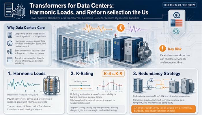
Most transformers are built for clean, linear loads. A data hall is the opposite. Racks of servers, storage, and network gear run on switch-mode power supplies, and the UPS that backs them up adds more. Those devices draw current in short pulses instead of smooth sine waves, and that pulsing is what we call harmonics.
A conventional dry-type unit rated for motors and lighting will run hotter than its nameplate suggests in this environment, even when the ammeter looks fine. The extra heat comes from losses that a normal load never produces.
If you are scoping a build, start with the data center transformer solutions overview, then drill into the three things that actually decide the spec: harmonic load, K-rating, and redundancy.
What harmonics do to a transformer
Three things happen when harmonic current shows up.
First, eddy-current and stray losses in the windings and enclosure rise with the square of the harmonic frequency. A 5th harmonic at 300 Hz does far more heating damage than the same amps at 60 Hz.
Second, the triplen harmonics (the 3rd, 9th, 15th, and so on) add up in the neutral conductor instead of canceling. A panel that looks balanced on the phases can still cook its neutral. That is why data center units get an oversized neutral, often rated at 200 percent of the phase conductors.
Third, the harmonic heating shortens insulation life. A unit that never trips and never overloads on the meter can still fail early because its hotspots ran 20 degrees hotter than the design assumed.
How much harmonic current are we talking about
Unfiltered server and UPS loads commonly land in the 15 to 30 percent total harmonic distortion range. A harmonic study on the actual IT load is the only way to pick the right K-rating with confidence. Guessing low is the single most expensive mistake in this whole category, because the transformer quietly degrades instead of failing loud.
K-Rating explained
K-rating is a number from ANSI/IEEE C57.110 that tells you how much harmonic heating a transformer can survive at full load. The scale runs K-1 (clean linear load) up through K-4, K-9, K-13, K-20, and beyond. For data centers, K-13 is the common floor for IT distribution, and K-20 is the norm for AI and GPU halls where the rectifier load is brutal.
Here is the part most specifiers miss.
The derating trap inside every K-rated nameplate
A K-rated transformer is not magically larger. Its nameplate kVA is the linear-load rating, and the K-rating just says it will tolerate harmonic heating without cooking. The usable capacity for a harmonic load is lower. Per the IEEE C57.110 derating basis, the effective capacity factors land close to this:
| K-rating | Typical environment | Harmonic load | Usable capacity at nameplate | Size-up factor |
|---|---|---|---|---|
| K-1 | Linear loads only | None | 100 percent | 1.00x |
| K-4 | Offices, light commercial | Light | 96 percent | 1.04x |
| K-13 | IT distribution, modern commercial | Moderate to heavy | 88 percent | 1.14x |
| K-20 | AI clusters, GPU farms, heavy VFD | Severe | 84 percent | 1.19x |
| K-30 to K-50 | Extreme rectifier environments | Very severe | 70 to 80 percent | 1.25x to 1.43x |
Read that middle column carefully. A 1,000 kVA transformer stamped K-13 can only deliver about 880 kVA of useful capacity on a harmonic-heavy IT load. Size it as if it were 1,140 kVA. A K-20 unit drops to about 840 kVA and needs to be treated like a 1,190 kVA unit. This is exactly why the practical sizing multipliers you see in the field land at 1.15x for K-13 and 1.25x for K-20. The nameplate number is not the number you plan around.
K-rated means tolerate, not fix
A K-rated transformer does not remove harmonics. It survives them. The harmonics still flow back onto the feeder and stress the upstream gear. If the utility or your own power quality budget demands cleaner power, you pair the K-rated unit with harmonic mitigation: 12-pulse or 18-pulse rectifiers on the UPS, passive or active filters on the low-voltage side, or a zigzag or delta-wye winding arrangement that traps the zero-sequence triplen current. Our K-rated dry-type project for a hyperscale data centre shows how this is built in practice.
How harmonics shape the physical build
Beyond the K stamp, harmonic loads change the hardware. The neutral conductor is oversized, the winding geometry is tuned to cut eddy losses, and the insulation class is bumped up (F or H) so the extra heat has somewhere to go. You also see lower flux density in the core to avoid saturation when the waveform gets ugly. None of this shows up on a basic price quote, which is why two transformers with the same kVA can be worlds apart in suitability.
Redundancy: N, N+1, 2N, and the maintenance question
Redundancy is about uptime math. The Uptime Institute tiers give you the language buyers and engineers already use.
| Topology | Installed capacity vs IT load | Where it is used |
|---|---|---|
| N (no spare) | About 1.0x plus growth margin | Tier I, non-critical |
| N+1 | About 1.3x to 1.5x, one redundant unit | Tier III |
| 2N | About 2.0x, two independent paths | Tier IV |
| 2(N+1) | About 2.3x to 2.5x | Tier IV high-security |
A common planning rule is that total installed transformer capacity lands near 1.5 times the IT critical load for N+1 and near 2.0 times for 2N, before you add harmonic derating on top. As a sanity check, a 10 MW critical load typically maps to roughly 20 MVA at N+1 and 30 MVA at 2N once you count spares and the two independent paths.
The installed-capacity multiplier, worked out
Take a 2 MW IT critical load at 0.95 power factor, served by K-20 units, with an N+1 requirement.
Base kVA is 2,000 divided by 0.95, or about 2,105 kVA. Apply the K-20 derating factor of 0.84 and the real requirement is 2,105 divided by 0.84, or about 2,506 kVA per operating unit. The next standard size up is 3,000 kVA. For N+1 you install two of them, so the hall carries 6,000 kVA of transformer for 2 MW of IT load. That is roughly three times the IT load, and most of the gap is harmonics and redundancy, not waste. Skip either one and the hall goes down when a single unit fails.
If the site has headroom and a tight budget, forced-air (AF) cooling can recover about 12 percent of nameplate capacity versus natural convection (AN), which sometimes lets you stay on a smaller standard size. The cooling class guide explains when AN versus AF pays off.
US-specific specs you cannot skip
A unit that is perfect on paper in an IEC market can be unsellable in the US. The gatekeepers are different.
Dry-type is the default indoors because there is no flammable fluid to manage near the racks, and the fire code is far simpler. That points you to UL 1561 for units up to 600 V and UL 1562 for the 601 V to 35 kV class. NEC Article 450 sets the installation and ventilation rules. For the room itself, NFPA 75 covers information technology equipment and NFPA 76 covers telecommunications, and both reach into how you place and protect the transformer.
Efficiency is a legal floor, not a nice-to-have. DOE 10 CFR 431 sets no-load and load-loss levels for distribution transformers, the 2016 levels are the current rule, and the 2024 update takes effect on 2029-04-23. Spec a unit that meets today and you still want the 2029 numbers in writing if the project commissions after that date.
Frequency is a trap. US gear is 60 Hz. A 50 Hz unit imported because the price looked good will run with higher flux density, higher no-load loss, and higher magnetizing current on a 60 Hz system, and it is not a simple relabel. If you are weighing IEC versus ANSI/IEEE compliance for a US delivery, the standards comparison breaks down what actually changes. Seismic bracing and altitude or ambient derating round out the list, and both depend on the exact site.
A data center transformer RFQ checklist
Hand your supplier this list and you will get comparable quotes instead of a pile of mismatched numbers.
- IT critical load in kW and the expected power factor
- Primary and secondary voltage, typically 13.8 kV in and 480Y/277 V out for US halls
- Required K-rating, backed by a harmonic study
- Redundancy target, N, N+1, or 2N, and the Tier you are building to
- Cooling method, AN, AF, or forced air
- Dry-type or liquid, driven by indoor location and fire code
- UL or cUL listing and the exact model scope it covers
- DOE 10 CFR 431 compliance date, 2016 now and 2029-04-23 soon
- Seismic and environmental limits, altitude and ambient temperature
- Monitoring, winding temperature, DGA for liquid units, remote alarms
- Testing, routine and type tests from an NRTL-recognized lab
- Quote validity window and lead time, because both move in 2026
The nameplate is where most of these values live, so the nameplate reading guide is worth a look before you sign. And the routine testing write-up tells you which test reports should arrive with the unit.
Common mistakes specifiers make
Specifying K-1 for a hall full of servers is the headline error. The unit will not trip, it will just age fast and fail early. Reading the nameplate kVA as usable kVA on a K-rated unit is the quiet one, because the derating factor is easy to forget. Under-sizing the neutral against triplen harmonics burns the conductor nobody is watching. Picking a redundancy level by habit instead of by Tier target overspends or underspends by a wide margin. Forgetting 60 Hz turns a cheap import into a doorstop. And treating K-rating as a harmonic filter lets the rest of the power system eat the distortion the transformer was only built to survive.
Bottom line
A data center transformer lives in the hardest electrical environment most units will ever see. Pick the K-rating from a real harmonic study, then size for the derating factor, not the sticker. Choose redundancy by the Tier you are committed to, and add the US listings, NEC 450, NFPA rules, and DOE efficiency before the unit is built, not after. Get those right and the transformer disappears into the background, which is exactly what you want from the one piece of gear that is supposed to never be noticed. If your hall is still on paper, talk to the TransNorth Electric team about a spec that clears the code and the budget at the same time.
FAQ
What K-rating do I need for a data center transformer? Most IT distribution uses K-13, and AI or GPU halls with heavy rectifier loads use K-20. K-4 fits light commercial loads. The number comes from a harmonic study, not a guess, because the usable capacity drops to about 88 percent at K-13 and 84 percent at K-20.
Does a K-rated transformer remove harmonics? No. A K-rated transformer tolerates harmonic heating without failing early. It does not clean the waveform. Pair it with 12-pulse or 18-pulse rectifiers, passive or active filters, or a zigzag winding if you need cleaner power upstream.
How much extra capacity does redundancy add? Plan for about 1.5 times the IT critical load at N+1 and about 2.0 times at 2N, before harmonic derating. A 10 MW critical load typically needs roughly 20 MVA at N+1 and 30 MVA at 2N once spares and the two independent paths are counted.
What US standards apply to data center transformers? Dry-type units need UL 1561 up to 600 V or UL 1562 for 601 to 35 kV, installed under NEC Article 450. NFPA 75 and NFPA 76 govern the equipment room. DOE 10 CFR 431 sets efficiency, with 2016 current and 2029-04-23 for the 2024 update.
Why is the neutral conductor oversized in data centers? Triplen harmonics, the 3rd, 9th, and 15th, add up in the neutral instead of canceling on the phases. That can overheat a normally sized neutral, so data center units commonly use a neutral rated at 200 percent of the phase conductors.
Can a 50 Hz transformer run on 60 Hz in the US? Not safely as a simple swap. A 50 Hz design runs at higher flux density on 60 Hz, which raises no-load loss and magnetizing current. US data centers are 60 Hz, and the unit should be designed for that frequency natively.
How do I size a K-20 transformer for a 2 MW load at N+1? At 0.95 power factor the base is about 2,105 kVA. Divide by the K-20 factor of 0.84 for about 2,506 kVA per unit, round up to 3,000 kVA, and install two for N+1. That is roughly 6,000 kVA of transformer for 2 MW of IT load.