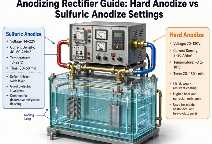
Hard anodize and sulfuric anodize use the same rectifier but opposite ends of its range. Type II sulfuric runs at 12–24 V and 1.2–1.8 A/dm² in an 18–22 °C bath, while Type III hardcoat ramps from about 24 V to 60–100 V at 2–4 A/dm² near 0 °C. The number most buyers get wrong is voltage, because you must specify the end-of-cycle peak, not the starting value.
If you remember one thing, make it this. The rectifier does not care whether you call the job hardcoat or decorative. It pushes current and it pushes voltage. What changes between the two processes is where you set those two knobs and how they move during the cycle. Sulfuric anodizing is a low-voltage, steady-current job. Hard anodizing is a high-voltage, ramping job that needs real headroom and low ripple. Get the voltage rating wrong and the coating turns soft before the cycle finishes. Get the ripple wrong and you get burning, striations and uneven film. This guide gives you the exact settings, explains why the published numbers disagree by two or three times, and walks through a full sizing example you can copy.
1. The two settings, side by side
Here is the whole answer in one table. These are working ranges for aluminium in sulphuric acid, quoted in both metric and the ASF units US shops still use. One A/dm² equals 9.2903 ASF.
| Parameter | Type II sulfuric (decorative) | Type III hardcoat |
|---|---|---|
| Output voltage | 12–24 V DC | 24 V start, ramping to 60–100 V at end of cycle |
| Current density | 1.2–1.8 A/dm² (11–17 ASF) | 2–4 A/dm² (19–37 ASF) |
| Bath temperature | 18–22 °C (64–72 °F) | 0–5 °C (32–41 °F), chilled |
| Ripple, max | ≤10% (≤5% preferred) | ≤5%, ≤2% for aerospace work |
| Typical film | 5–25 µm | 25–100 µm |
| Control mode | Constant current, or CC with a CV ceiling | Constant current with programmable ramp, CV ceiling above peak |
| Rectifier type | Thyristor (SCR) or IGBT | IGBT preferred, with ramp control |
Two numbers jump out. Hardcoat asks for roughly twice the current density and up to four times the voltage. Push both at once and the DC power goes up about eight times for the same loaded area. That is why a hardcoat line needs a bigger transformer, heavier busbar and a chiller, and why you cannot assume a decorative-anodize supply will do the job.
What these numbers actually control
Current density sets how fast the oxide grows and how dense it is. Voltage is not an independent target. It is the pressure the supply needs to keep that current moving as resistance climbs. Time then sets thickness. If you run 2 A/dm² for 45 minutes, you are putting a known charge through the surface, and the film grows to roughly the thickness the spec calls for. Change the alloy or the bath and the voltage needed to hold those amps changes, but the amps still rule the film.
2. Why the voltage numbers in other articles do not match
Search this topic and you will find sulfuric anodize quoted at 12–18 V in one place, 15–20 V in another and 12–24 V in a third. Hardcoat gets quoted at 24–60 V, 25–75 V, 30–75 V and even 100 V. Nobody explains the gap. All of those numbers can be right at the same time, because they are measuring different moments and different loads.
Voltage is current times resistance
The relationship is simple: V = I × R. The resistance the supply sees has three parts.
Where the resistance comes from
- Bath resistance. Set by acid concentration, dissolved aluminium and temperature. Cold, low-conductivity electrolyte means higher resistance.
- Oxide resistance. Aluminium oxide is an insulator. As the film thickens, this term grows, and it grows a lot.
- Circuit resistance. Busbar, cable, rack contacts and the part itself. A 6 m copper bus run at 2,000 A can drop 2–3 V on its own.
At the start of a hardcoat run the film is thin, so the supply might sit at 24–30 V. By the end, the oxide has built up and the same 3 A/dm² may take 60–80 V. The supply raises voltage on its own to hold current. The rating you specify has to cover that last minute of the cycle, not the first.
Six reasons the ranges differ
- Start point or end point. A source quoting 24 V may mean where the ramp begins. A source quoting 100 V means where it ends. Same job, two moments.
- Alloy. A 6061 part anodized to 50 µm might finish at 40–60 V. A high-silicon 4xxx alloy can pass 80 V for the same thickness.
- Target thickness. More oxide means more resistance. A 25 µm film and a 100 µm film on the same alloy do not finish at the same voltage.
- Bath temperature and chemistry. Colder and more dilute baths push resistance up. Mixed organic electrolytes are sold specifically for lower voltage operation, which is why one technical paper lists hardcoat at only 0–50 or 0–75 V.
- Bus and contact losses. Long cable runs and dirty rack contacts add volts that show up on the supply’s meter but never reach the part.
- Ripple and control method. A full-wave supply with poor filtering reads differently from a switch-mode unit under the same load.
The consequence for your spec
Write the end-of-cycle peak voltage on the RFQ, with the alloy and target thickness next to it. If a vendor quotes a 24 V unit for hardcoat, ask what happens at minute 90. When a rectifier hits its voltage ceiling, it stops being able to hold current. The current falls, the film stops growing properly, and you pull a soft, thin coating out of the tank. Under-voltage at the end of the cycle is one of the most common causes of rejected hardcoat, and it is almost always a specification mistake rather than a machine fault.
For the transformer feeding the rectifier, the same logic applies. If you are building a new line, our application-specific solutions cover how the power stage is matched to the process, and our industrial and metallurgy power notes go deeper on supply-side sizing.
3. Constant current, constant voltage, and where they switch
Most anodizing confusion comes from treating CC and CV as two different machines. They are two modes of the same supply, and you use them at different points in the cycle.
Run the film in constant current
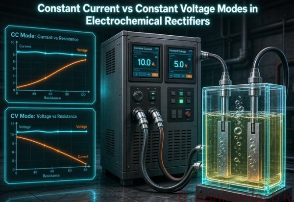
In CC mode the supply holds amps at your setpoint and lets voltage float upward as the oxide grows. This is what you want for both processes. Film thickness tracks charge, so holding current gives you a repeatable coating. In CV mode the supply holds voltage and lets current fall as resistance rises. That produces a thinner film than the operator expected, which is why CV as the primary mode is a bad default for anodizing.
Use CV as a ceiling, not a target
The useful trick is to run CC with a voltage ceiling set above the highest voltage you expect. Think of the crossover resistance:
Rc = Vset / Ilimit
While the load resistance stays below Rc, the supply is in CC and voltage climbs toward the ceiling. If resistance rises past Rc, the supply switches to CV and current backs off. That switch protects the part. It stops a rising-resistance fault from driving voltage to the rail and burning the work. Set Vset near the end-of-cycle peak plus 10–15% headroom, and set Ilimit at the current density you actually want.
Ramp the first minutes
Full current applied at second zero on a cold, low-resistance bath crowds into edges, corners and high spots. Those areas burn while the flats are still thin. A programmable ramp fixes this. Raise voltage gradually, typically 0.5–2 V per minute, or step current up over the first minutes until the oxide establishes. Hardcoat needs this more than decorative work because the current densities are higher and the bath is colder. The supply should let you store the ramp profile as a recipe so every shift runs the same curve.
That distinction between a process variable and a protective limit is the same one we draw across our technical resources library on rectifier and converter duty.
4. Ripple, ramp and the specs buyers forget to write down
Ask a buyer what they specified and you often get two numbers: amperage and voltage. The specification that decides whether the coating is any good never makes the page.
What ripple does to the film
Ripple is the AC component left on the DC output, expressed as a percentage. Think of it as the current dipping and peaking many times a second. When it dips, local current density falls below the level needed to grow dense oxide. The film comes out uneven, with micro-porosity at grain boundaries and softer spots where the troughs landed. Push the average current up to compensate and the peaks start burning edges. High ripple also adds harmonic heating, which warms the bath and makes temperature control harder.
The practical rules of thumb:
Ripple limits by process
- Decorative Type II: ≤10% ripple is generally acceptable.
- Hardcoat Type III: ≤5%, with ≤2% commonly cited for aerospace and defence work under MIL-A-8625 Type III. Confirm the exact figure against your purchase spec, not a blog.
- Precious-metal and fine-feature work: below 2%, where the process allows it.
Two ways to keep ripple low. Run the supply close to its rated current, because ripple ratio gets worse at light load, and pick switch-mode (IGBT) over thyristor where the process is sensitive. There is a deeper treatment of ripple and regulation in our special transformers background material on converter supplies.
IGBT or thyristor
Thyristor (SCR) rectifiers are cheaper and fine for decorative sulphuric work. They run around 0.85 power factor and their ripple is harder to control. IGBT units switch much faster, give lower ripple, better power factor around 0.92 to 0.95 and far more precise ramp control. They usually cost 15–25% more for the same rating. For hardcoat, complex geometries or any spec with a ripple clause, the IGBT premium pays for itself in fewer rejects.
Cooling and duty cycle
Air cooling is simple and works up to roughly 5,000 A in a clean shop. Above that, or on continuous duty, water cooling handles the heat better but adds plumbing and leak checks. State the duty cycle and the inlet water temperature on the RFQ. A supply rated for intermittent duty will overheat on a line that runs two shifts.
5. A worked example: 1,000 dm² loaded on both processes
Numbers stick better than rules. Here is the same tank area sized two ways. Assume 1,000 dm² of loaded surface, counted on both sides, a 25% headroom factor for rack resistance and future capacity, and an IGBT supply at 0.92 power factor. Rated current rounds up to the next standard size.
Type II sulfuric
- Base current: 1,000 dm² × 1.5 A/dm² = 1,500 A
- With 25% headroom: 1,500 × 1.25 = 1,875 A, round to 2,000 A
- End voltage: 20 V
- DC power: 2,000 × 20 / 1,000 = 40 kW
- Transformer: 40 / 0.92 = 43.5 kVA, select 50 kVA
- Ramp: not critical, low ripple preferred, ≤10% acceptable
Type III hardcoat
- Base current: 1,000 dm² × 3.0 A/dm² = 3,000 A
- With 25% headroom: 3,000 × 1.25 = 3,750 A, round to 4,000 A
- End voltage: 80 V, the peak the supply must reach
- DC power: 4,000 × 80 / 1,000 = 320 kW
- Transformer: 320 / 0.92 = 348 kVA, select 400 kVA or split into 2 × 2,000 A units
- Ramp: 0.5–2 V/min programmable, ripple ≤5%, CV ceiling near 90 V
Same tank, same area, eight times the DC power. Current doubled, voltage quadrupled. This is the calculation that should happen before anyone talks about price. If you want the arithmetic run for your own loaded area and alloy, you can talk to our engineering team with the figures below.
Busbar and cable check
Copper busbar is commonly sized around 1 A per mm² of cross-section for continuous duty. A 2,000 A output needs about 2,000 mm², often built as 4 × 500 mm² flat bars. Aluminium needs roughly 1.6 times that area. Add the voltage drop to your headroom, because a long run at high current eats into the volts available at the tank.
6. What to put on your RFQ
A good anodizing rectifier enquiry is short but complete. Copy this list and you will get comparable quotes instead of guesses.
- Process: Type II sulfuric, Type III hardcoat, or both on one line.
- Loaded surface area in dm², counting both sides, at peak simultaneous load.
- Alloy and temper, for example 6061-T6 or 7075-T6, plus any high-silicon grades.
- Target film thickness in µm and the governing finish spec.
- Current density in A/dm² and the ASF equivalent if your shop uses both.
- Voltage at end of cycle, not just start, with the alloy and thickness it refers to.
- Ripple limit as a percentage, and whether an aerospace clause applies.
- Control mode: CC primary, CV ceiling value, and the ramp profile you need.
- Cooling type, duty cycle and inlet water temperature if water cooled.
- Mains supply: voltage, phase and 50 Hz or 60 Hz.
- Standards and inspection: which editions your customer requires.
Standards worth naming, with a caution
| Designation | Covers | Note |
|---|---|---|
| MIL-A-8625 | Type II and Type III anodize finishes, US DoD | Confirm current revision and class with your customer |
| IEC 60146 | Semiconductor power converters, the rectifier | Confirm current edition before tender |
| IEC 61378-1 | Industrial rectifier transformers | Confirm current edition; applies to the feeding transformer |
| ISO 7599 | General specification for anodic oxide coatings | Confirm current edition |
| ASTM B117 | Salt spray corrosion testing | A test method, not a rectifier spec; confirm current edition |
Standard designations are stable, but editions change and clauses get renumbered. Confirm the current revision before you write a number into a contract. We do not print clause-level limits here because the wrong edition on a tender is worse than no citation at all. Examples of finished work and how we document it are in our delivered projects section, and the broader complete product catalogue shows the supply options that sit behind these rectifiers.
FAQ
What voltage and current does a Type II sulfuric anodizing rectifier need?
Plan on 12–24 V DC and 1.2–1.8 A/dm², which is about 11–17 ASF. Hold the bath at 18–22 °C. Ripple of 10% or less is usually acceptable for decorative work.
What are the settings for Type III hard anodizing?
Start near 24 V and allow the supply to ramp to 60–100 V by the end of the cycle. Run 2–4 A/dm², roughly 19–37 ASF, in a bath held at 0–5 °C. Specify ripple of 5% or less, and check whether your spec calls for 2%.
Why does the voltage climb during an anodizing cycle?
Because aluminium oxide is an insulator. As the film thickens, its resistance rises, and V = I × R means the supply must raise voltage to hold the same current. The voltage at minute one tells you very little about the voltage at the end.
Why do different sources quote voltages that are two or three times apart?
Mostly because they describe different moments or different loads. Some quote the start of the ramp, some the end. Alloy, target thickness, bath temperature, electrolyte type and busbar loss all shift the number. A 6061 part at 50 µm and a high-silicon alloy at 100 µm are not the same job.
Should I run anodizing in constant current or constant voltage?
Constant current should be the primary mode, because film thickness follows charge. Use a constant-voltage ceiling as a safety limit set above the expected peak. The crossover is Rc = Vset / Ilimit.
What ripple is acceptable for hard anodize?
Five percent or less is the common rule of thumb. Aerospace and defence work under MIL-A-8625 Type III is often cited at 2% or less, but confirm the exact figure in your purchase spec. Decorative Type II usually tolerates up to 10%.
Why do I need a programmable current ramp?
Full current at the start crowds into edges and high spots on a cold, low-resistance bath and burns them. Raising voltage at roughly 0.5–2 V per minute lets the oxide form evenly. Store the profile so each batch repeats.
How do I size the transformer for an anodizing rectifier?
Calculate DC power as P(kW) = V × I / 1,000 using end-of-cycle voltage, then divide by power factor to get kVA. For 4,000 A at 80 V and 0.92 PF: 320 kW / 0.92 = 348 kVA, so select 400 kVA.
Is an IGBT rectifier worth the extra cost over thyristor?
For hardcoat, complex shapes or any ripple clause, yes. IGBT units give lower ripple, better power factor and tighter ramp control, typically for 15–25% more capital cost. For decorative Type II, thyristor is often enough.
Can I use a decorative 24 V anodizing rectifier for hardcoat?
Only if your alloy and thickness genuinely finish below 24 V, which is rare. Most hardcoat runs need 40–100 V at the end. A 24 V supply will current-limit early and produce a soft, thin film.
What information do you need to quote an anodizing rectifier?
Send loaded surface area in dm², alloy, target film thickness, process type, end-of-cycle voltage, current density, ripple limit, ramp profile, cooling and duty cycle, mains supply, and any standards your customer names. With those twelve items we can return a comparable specification and price.
Bottom line
Hardcoat and sulfuric anodizing are not two different machines. They are two operating points on one supply. Sulfuric sits low and steady at 12–24 V and 1.2–1.8 A/dm². Hardcoat climbs high and hot at 2–4 A/dm² and up to 100 V, cold bath and all. The setting that decides whether the part passes is the end-of-cycle voltage, backed by low ripple and a controlled ramp. Spec those three, and the rest of the line has a chance to hold tolerance.