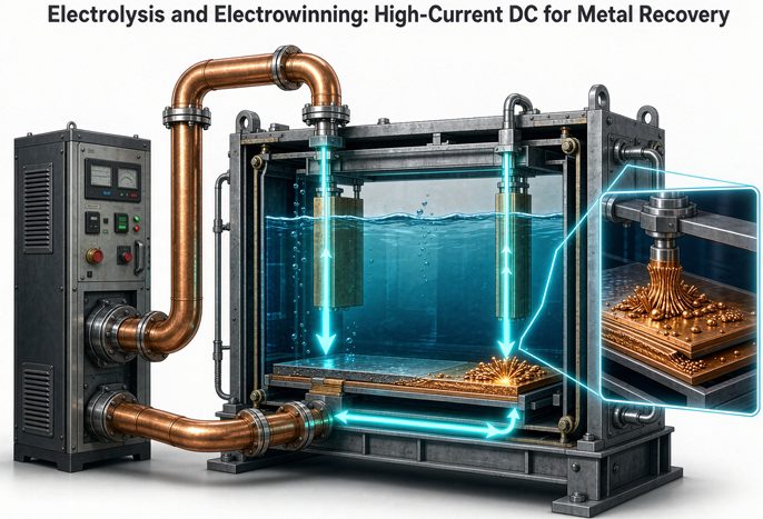
Electrolysis and electrowinning turn AC into controlled low-voltage, high-current DC: a copper cell runs near 2.0 V and 200 to 400 A/m², so 50 cells in series stack to about 100 V while total cathode area sets the bus at 10 to 50 kA, and Faraday’s law, not voltage, decides the tonnes per day.
If you are writing a spec for a metal recovery line, that sentence is the whole job in miniature. Get the three numbers wrong and you either buy a rectifier that cannot reach the cell voltage, or a transformer that cooks at full current, or a plant that never makes its tonnage. This guide walks the chain from a tonne of metal back to the kVA on the nameplate, in the order an engineer actually checks it. We are a transformer product range supplier, so we will stay honest about where the rectifier vendor’s job starts and ours ends.
The 10-second version. Cell voltage sets DC volts (about 2.0 V × number of cells in series). Cathode area times current density sets DC amps. Faraday’s law sets mass. DC power is their product, and the transformer must feed it at the right pulse count. Everything else is detail.
1. Electrolysis, electrowinning, electrorefining: the difference that changes your DC spec
Buyers use the three words loosely. The physics behind each one asks a different question of the power supply, so it is worth pinning down before you size anything.
1.1 The one-line difference
Electrolysis is the umbrella term: you push a non-spontaneous reaction with current. Electrowinning (EW) pulls metal out of a leach solution onto a cathode, usually after solvent extraction, with an inert anode. Electrorefining moves metal from a soluble impure anode to a clean cathode and drops precious metals into the anode slime.
| Question | Electrowinning | Electrorefining | Aluminum smelting |
|---|---|---|---|
| Where is the metal first? | Dissolved in electrolyte | In a soluble anode | Dissolved in molten cryolite |
| Anode | Inert (lead alloy or MMO) | Soluble, impure metal | Carbon, consumed |
| By-product | Oxygen at the anode | Precious-metal slime | CO₂ |
| Typical cell voltage | 1.8 to 2.2 V (Cu) | 0.2 to 0.4 V (Cu) | 4 to 5 V |
| Typical DC current | 12 to 50 kA (Cu), 12 to 120 kA (Zn) | 10 to 40 kA | 300 to 400 kA per potline |
| Current efficiency | 85 to 95% | 90 to 97% | 90 to 96% |
That voltage column is the first trap. Electrorefining runs at a fraction of a volt because the anode does the work of dissolving. Electrowinning has to split water at the anode, and that oxygen evolution costs roughly 0.5 V of overpotential. You do not size an EW rectifier from an ER data sheet.
1.2 Why the label matters to the rectifier
The industrial metallurgy transformer solutions we build around fall into two families, and the boundary is the anode reaction. Soluble-anode refining is a low-voltage, high-current job with tight regulation. Inert-anode winning is a higher-voltage job where anode condition and acid mist drive maintenance. Same plant, different failure modes, different instruments on the rectifier.
2. The three numbers that rule every tankhouse
Here is the part most product pages skip. Amps, volts and tonnes are three separate questions. Conflating them is how a buyer ends up with a 40 V supply on a line that only ever needs 110 V, or a 12 kA bus on a cathode area that wants 30 kA.
2.1 Voltage comes from cells in series
One copper EW cell sits around 1.8 to 2.2 V under load. That is too low to rectify efficiently on its own, so cells are wired in series. The DC bus voltage is simply the count times the cell voltage:
V_dc = N_cells × V_cell + bus and contact drop
A 50-cell line at 2.0 V is a 100 V bus. Add a few volts for busbar and contacts and the rectifier is specified around 110 to 120 V. A zinc line runs hotter: 3.2 to 3.6 V per cell, so 200 cells is a 640 to 720 V bus, which is why the European rectifier maker ETS lists zinc duty at 700 to 900 V while copper lands at 200 to 400 V. Same arithmetic, different cell count.
2.2 Current comes from cathode area
The current through the series circuit is set by how much cathode you hang in each cell and how hard you push it:
I = A_cathode,total × j
Where A is the plated area in m² (both sides of every cathode) and j is current density in A/m². Copper EW typically runs 250 to 350 A/m²; zinc 400 to 600 A/m². A cell with 54 cathodes of 2.04 m² each gives 110 m² of plated area. At 300 A/m² that cell draws 33 kA. At 260 A/m² it draws 28.6 kA. The published 10,000 t/yr copper plant in Peru uses exactly this layout: 54 cathodes, 2.04 m² each, 50 cells, a 120 V / 35 kA rectifier.
2.3 Mass comes from Faraday, not volts
This is the first-principles hook that clears up half the confusion in the market. Faraday’s law says deposited mass tracks charge passed, with voltage nowhere in the equation:
m = M × I × t × η / (n × F)
With F = 96,485 C/mol (26.8 Ah/mol), copper’s atomic mass 63.546 g/mol and n = 2, one ampere-hour plates 1.1856 g of copper at 100% efficiency. Flip that around: it takes 843 Ah to plate one kilogram at 100%, or about 937 Ah/kg at 90% current efficiency. That is the 0.9 to 1.0 kAh per kg figure you see in pilot-plant data, and it is arithmetic, not a vendor claim.
Specific energy follows from the same place. Because 1 kWh/t equals 1 Wh/kg numerically:
kWh/t = V_cell × (843 / η)
At 2.0 V and 90% efficiency that is 1,874 kWh/t. At 2.0 V and 91.7% it is 1,840 kWh/t, which matches the open hydrometallurgy textbook from BCcampus exactly. Push the cell to 2.2 V and the same line draws 2,062 kWh/t. That 0.2 V costs 10% of the power bill and buys a little more output per square metre. The trade is real, and it is priced in volts, not in marketing.
3. Worked example: a 10,000 t/yr copper line
Let me put the three numbers together so you can check every step. Assume 330 operating days a year, 90% current efficiency, 2.0 V per cell and 300 A/m² current density.
3.1 From tonnes to ampere-hours
10,000 t ÷ 330 days = 30.3 t/day, or 1,263 kg per hour. At 937 Ah/kg that is 1.18 MAh per hour, which is the same as saying the sum of current across all series cells is about 1,183 kA.
3.2 Choosing the series-parallel split
The series count is your choice, and it trades current against voltage while total DC power stays put:
| Cells in series | Bus current | Bus voltage | DC power | Plated area per cell |
|---|---|---|---|---|
| 50 | 23.7 kA | 100 V | 2.37 MW | 79 m² |
| 100 | 11.8 kA | 200 V | 2.37 MW | 39 m² |
| 200 | 5.9 kA | 400 V | 2.37 MW | 20 m² |
Same plant, same 2.37 MW. Fifty cells at 23.7 kA needs 79 m² of cathode per cell (40 cathodes at about 2 m² of plated area each). Two hundred cells halves the bus current but doubles the cell count and the cell house length. Most copper tankhouses land between 50 and 150 cells per circuit, which is why 200 to 400 V shows up as the catalog envelope.
The check that catches a bad spec
Multiply back. 50 cells × 100 V… no: 50 cells × 2.0 V = 100 V, times 23.7 kA = 2.37 MW. Over 7,920 hours that is 18.7 GWh, and 18.7 GWh ÷ 10,000 t = 1,874 kWh/t. It closes. If your numbers do not close on this loop, the spec is wrong somewhere.
3.3 The power bill
At $0.08/kWh, 18.7 GWh is about $1.50M a year. Dropping average cell voltage from 2.0 V to 1.8 V through cleaner electrolyte, closer anode spacing or better anodes saves roughly $150k a year on this line. That is why a tenth of a volt is worth a design review, and why a rectifier that holds steady current matters more than one with a glossy efficiency number on the brochure.
4. From DC demand to rectifier transformer
Now convert 2.37 MW of DC into something you can put on a purchase order. This is where our side of the line starts.
4.1 Sizing the kVA
Apparent power for the rectifier transformer is:
S = P_dc / (η_rect × kf × cosφ)
Use η_rect = 0.97, a 6-pulse form factor kf of about 1.05, and cosφ = 0.95. The product is 0.968, so 2.37 MW needs about 2.45 MVA. Add 10% for harmonic heating and you are at 2.7 MVA. A practical layout is three 1,000 kVA units in an n+1 arrangement, so one can be pulled for maintenance without stopping the line. European rectifier builders commonly quote n-1 operation, meaning full rated DC with one semiconductor out of a leg; that is a control feature, not extra transformer capacity, so do not count it as your spare.
4.2 Secondary voltage and the 1.35 rule
For a 6-pulse bridge the no-load DC voltage is roughly 1.35 × the line-to-line secondary RMS voltage. A 100 V bus therefore wants about 75 to 80 V secondary before regulation margin, and a 12-pulse series arrangement doubles that relationship. Treat these as starting points and have the rectifier vendor confirm the firing angle and OLTC range; the power-frequency furnace transformer family we build shares the same low-voltage, high-current secondary design discipline, but the firing duty is not identical.
4.3 Pulse count, phase shift, and why 12 beats 6
A 6-pulse bridge puts characteristic harmonics at h = kp ± 1, so 5th, 7th, 11th, 13th, with amplitudes near 1/h. Two 6-pulse bridges shifted by 30° cancel the 5th and 7th and leave 11th and 13th first. Four bridges at 15° apart push the first residual to the 23rd.
| Pulse count | Phase shift between bridges | First residual harmonic | Ideal THD | DC ripple at 60 Hz |
|---|---|---|---|---|
| 6 | n/a | 5th | 31.1% | 360 Hz |
| 12 | 30° | 11th | 15.2% | 720 Hz |
| 24 | 15° | 23rd | 7.6% | 1,440 Hz |
The shift angle is 360°/p, so 12-pulse is 30° and 24-pulse is 15°. Doubling pulse count cuts ideal THD to roughly half, not exactly half (0.490 for 6 to 12, 0.497 for 12 to 24). If someone tells you 24-pulse is “exactly half of 12,” they are rounding.
5. Ripple, regulation, and cathode quality
5.1 Ripple frequency and what it does to the plate
Ripple frequency is pulse count times line frequency: 360 Hz for 6-pulse at 60 Hz, 300 Hz at 50 Hz. High-frequency IGBT units push this into the kHz range and can hold ripple under 2%. Why care? Ripple modulates the deposition rate across a cycle, and rough or dendritic cathodes show up first where the waveform is dirtiest. For base-metal EW, a few percent ripple is usually tolerable; for precious-metal recovery, buyers ask for under 2%.
5.2 Constant current is the default
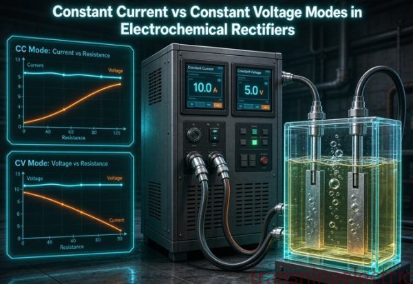
Current decides how much metal plates per hour. Hold current steady and output is steady; let it sag and current efficiency drops while impurities ride along. So EW rectifiers sit in constant-current mode almost all the time. Constant-voltage is a ceiling, used to protect the circuit if resistance climbs (anode passivation, a cell going dry, a bad contact).
The crossover worth understanding
Every CC/CV supply has a crossover resistance, R_c = V_set / I_limit. If the load resistance is below R_c the unit behaves as a current source; above R_c it behaves as a voltage source. A loose busbar contact looks exactly like poor current efficiency on the meter, and the rectifier will happily report it. This is why thermal imaging of contacts comes before blaming the power supply.
6. Harmonics and IEEE 519 at the PCC
6.1 The table buyers get wrong
IEEE 519-2022 sets current distortion limits based on the short-circuit ratio at the point of common coupling, not on the transformer nameplate. The total demand distortion (TDD) column is the one that catches a rectifier plant:
| Isc/IL at PCC | Individual 5th limit | TDD limit |
|---|---|---|
| < 20 | 4.0% | 5.0% |
| 20 to 50 | 7.0% | 8.0% |
| 50 to 100 | 10.0% | 12.0% |
| 100 to 1,000 | 12.0% | 15.0% |
| > 1,000 | 15.0% | 20.0% |
A weak grid with Isc/IL under 20 allows only 5% TDD. A 6-pulse line at 31% ideal THD has no chance there; you need 12 or 24 pulse, or an active filter. On a stiff grid above 1,000 the limit is 20% and a well-filtered 12-pulse passes. Same equipment, opposite verdict, decided by the grid you connect to.
6.2 What 519 does and does not measure
TDD uses the maximum demand load current as its denominator, measured at the PCC over a statistical window. Daily 99th percentile current must stay under twice the table value, weekly 99th under 1.5 times, and weekly 95th under the table value. Those bands do not rescue a plant that runs over limit all day. Also note that the 2022 revision changed the even-harmonic treatment from the 2014 edition; check the current text before you write a guarantee into a contract.
For a cross-border project the standard stack gets layered, and our guide to IEC and ANSI/IEEE standards for export transformers explains how IEC 60146 (semiconductor converters) and IEC 61378-1 sit alongside IEEE 519 and IEEE C57.18.10. Confirm the current edition of each before you sign.
7. Process envelope by metal
Use this as a sanity check on a supplier’s numbers. Ranges are starting points from industry practice, not design values; your electrolyte decides the real figures.
| Metal | Cell voltage | Current density | Current efficiency | Specific energy |
|---|---|---|---|---|
| Copper EW | 1.8 to 2.2 V | 250 to 350 A/m² | 88 to 95% | 1,800 to 2,200 kWh/t |
| Zinc EW | 3.2 to 3.6 V | 400 to 600 A/m² | 85 to 92% | 3,000 to 3,500 kWh/t |
| Nickel EW | 3.0 to 4.0 V | 200 to 400 A/m² | 90 to 96% | 2,800 to 3,400 kWh/t |
| Cobalt EW | 3.0 to 4.0 V | 200 to 350 A/m² | 88 to 94% | 3,000 to 3,600 kWh/t |
| Gold (cyanide) | 1.5 to 2.5 V | 50 to 150 A/m² | 95 to 99% | process specific |
| Aluminum | 4 to 5 V | ~10,000 A/m² | 90 to 96% | 13,000 to 15,000 kWh/t |
Zinc costs nearly twice copper per tonne because the cell voltage is higher, not because the current is higher. Aluminum is in another universe entirely. If a quote gives you one “electrolysis rectifier” for all three, keep looking.
8. Five mistakes that cost money
8.1 Specifying voltage without cell count
A 120 V rectifier is meaningless unless I know how many cells are in series and what each one draws at end of cycle. Voltage rises as anodes passivate and electrolyte cools. Size for the worst point in the cycle, not the average.
8.2 Buying on kW and ignoring kA
Two 2.4 MW rectifiers are not interchangeable. One at 100 V / 24 kA needs busbar that a 400 V / 6 kA unit never sees. Busbar loss is I²R: 8,000 A through 100 µΩ drops 0.8 V and throws 6.4 kW into the room. At 24 kA the same resistance becomes 58 kW. Copper cross-section is a design decision, not a cable schedule afterthought.
The busbar check
Ask for the bus resistance per metre and the total run length, then multiply I²R yourself. If the vendor cannot give you both numbers, that is an answer.
8.3 Assuming 6-pulse will pass harmonic compliance
See section 6. The PCC ratio decides this, and the utility usually decides the ratio.
8.4 Treating published energy savings as a guarantee
Product pages advertise 8% to 12% or 20% savings against thyristor sets. Those are vendor claims with no test basis in the sources we found. Ask for a measured before-and-after at the same current density and electrolyte, or ignore the number.
8.5 Skipping the electrolyte testwork
One selection guide says it plainly: shake-out tests, then a continuous pilot, then acceptance tests tied to payment. A supplier who quotes without your PLS analysis is quoting a guess. The same goes for the rectifier, because your current efficiency sets the kA, and your cell voltage sets the V.
9. What to send in an RFQ
A short list gets you a real quote instead of a brochure:
- Metal and route (EW, ER, smelting) and annual tonnes.
- PLS or electrolyte assay, temperature, and acid or cyanide range.
- Cells in series, cathodes per cell, plated area per cathode.
- Target current density and expected range.
- Cell voltage at start and end of cycle.
- Current efficiency you are designing to, and the basis for it.
- Duty hours per year and site ambient conditions.
- Grid fault level at the PCC (Isc/IL) and the utility’s harmonic clause.
- Preferred pulse count, or ask us to propose one.
- Redundancy requirement (n+1, n-1, or single line).
- Cooling medium and available water quality.
- Whether CC, CV, or automatic crossover is required.
Send those twelve and any competent rectifier or transformer builder can price it. We review reference projects with buyers on exactly this checklist before we quote a transformer.
10. Standards and what to verify
| Standard | Covers | Buyer action |
|---|---|---|
| IEC 60146 | Semiconductor converters | Confirm current edition with rectifier vendor |
| IEC 61378-1 | Converter transformers for industrial drives and rectifiers | Ask for the temperature-rise and harmonic-loss basis |
| IEEE C57.18.10 | Semiconductor rectifier transformers | Check the impedance and loss guarantee |
| IEEE 519-2022 | Harmonic control at the PCC | Get the site Isc/IL in writing |
| IEC 60076 series | Power transformer general and temperature rise | Use as the base spec for the transformer |
We did not purchase the full text of any standard for this article. Treat the table as a map of what to ask, not as a compliance statement. Where two sources disagree on an edition or a limit, we report both rather than pick one.
FAQ
What voltage does a copper electrowinning rectifier need?
About 1.8 to 2.2 V per cell, multiplied by the number of cells in series, plus a few volts for bus and contact drop. A 50-cell line runs near 100 V and is usually specified at 110 to 120 V. Zinc runs higher at 3.2 to 3.6 V per cell, so a 200-cell zinc line is a 640 to 720 V bus.
How much current does electrowinning draw?
For copper, 250 to 350 A/m² of plated cathode area is typical. A cell with 110 m² of plated area at 300 A/m² draws 33 kA. Industrial copper lines typically run 12 to 50 kA, zinc 12 to 120 kA, and aluminum potlines 300 to 400 kA.
How many ampere-hours per kilogram of copper?
843 Ah/kg at 100% current efficiency from Faraday’s law, about 937 Ah/kg at 90%, and roughly 992 Ah/kg at 85%. That is where the 0.9 to 1.0 kAh per kg rule of thumb comes from.
Why is electrowinning high current and low voltage?
Because each cell only needs about 2 V, and cells are wired in series to raise the bus voltage. The current has to serve every cathode at once, so it scales with total plated area. Fix the tonnage and the series count trades current against voltage while DC power stays constant.
What is the specific energy of copper electrowinning?
About 1,800 to 2,200 kWh per tonne. At 2.0 V and 90% current efficiency the arithmetic gives 1,874 kWh/t. Cell voltage moves it most: 2.2 V raises it to about 2,062 kWh/t at the same efficiency.
Is electrowinning the same as electrorefining?
No. Electrowinning deposits metal from a leach solution onto a cathode with an inert anode and produces oxygen. Electrorefining dissolves an impure soluble anode and deposits pure metal, with precious metals falling as slime. Refining runs at 0.2 to 0.4 V per cell; winning runs at 1.8 to 2.2 V for copper.
Does Faraday’s law include voltage?
No. Deposited mass equals atomic mass times current times time times efficiency, divided by electron count and Faraday’s constant. Voltage affects energy use and deposit quality, not the mass per ampere-hour.
Why do I need more than 6 pulses?
Six-pulse rectification has about 31% ideal current THD with 5th and 7th harmonics dominant. Twelve-pulse with a 30° phase shift cancels those and starts at the 11th, dropping ideal THD to about 15%. If your PCC has Isc/IL under 20, IEEE 519 allows only 5% TDD and 6-pulse will not comply.
Constant current or constant voltage for electrowinning?
Constant current for production, because mass tracks charge. Constant voltage acts as a ceiling if resistance climbs. The crossover resistance is the set voltage divided by the current limit; below it the supply behaves as a current source, above it as a voltage source.
What information do you need to quote a rectifier transformer?
Metal and route, annual tonnes, electrolyte assay and temperature, cells in series, cathodes per cell, plated area, current density, cell voltage at start and end of cycle, current efficiency basis, duty hours, grid fault level at the PCC, pulse count, redundancy, and cooling. Twelve lines is enough for a first pass.